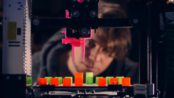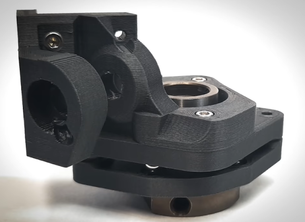
Dual extrusion systems for 3D printers have been around for quite a few years, but the additional cost, complexity, and hassle of printing with them have kept them off the workbenches of most hackers. [Jón Schone] from Proper Printing has now thrown his own hat in the ring, with a custom dual extrusion rocker system that can swap extruders without any additional actuators.
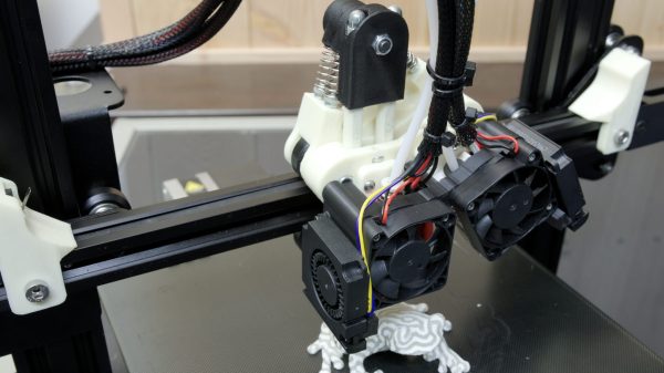
The two extruders are mounted on a spring-loaded rocker mechanism, which holds the inactive extruder up and away from the printing surface. Extruders are swapped by moving the carriage to either end of the x-axis, where the v-wheel rolls a ramp and pops the rocker over, putting the new extruder in the center line of the carriage. There are 3 wheels at the top of the carriage, but only two are in contact with the rail at any time. While this system is more complex than simply mounting two extruders side-by-side, it reduces the chances of the inactive nozzle oozing onto the parts or scraping across the surface. The height of each extruder can be adjusted with a screw, and any horizontal offset between the nozzles is checked with a calibration procedure and corrected in the firmware. See the full video after the break.
[Jón] is offering the design files and modified firmware to perform this mod on your own Ender 3 Pro (though he notes other Creality printers should be compatible), but you’ll still need to source a control board with the additional stepper driver and heater output for the second extruder. This is yet another in a long list of hacks he’s performed on this popular entry-level printer, such as a modification that allows you to fold the machine up and take it on the go.