Electromagnetic 7-Segment Display Easy On The Eyes AND The Ears

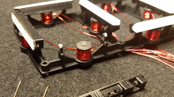
We love electromagnetic displays: take the modern look of a digital readout, combine with the low-tech coil mechanism that you theoretically could create yourself, add a dash of random clacking sounds, and what’s not to like? Evidently, [Nicolas Kruse] shares our affection for these displays, because he’s taken it beyond theory and created a 7-segment magnetically-actuated display from scratch.

The display is 3D-printed, as you would expect these days. Each segment contains a small neodymium magnet, and each coil a 1 mm iron core for flux concentration. The coils are driven with a 1.6 A peak current, causing the segments to flip in less than 10 ms. [Nicolas] provides STL files for the display base, segments, and spools so you can print your own display. He’s also released the schematics and code for the driver, which uses an ATtiny44 to drive the coils through N- and P-channel MOSFETs. Initially designed to drive a passive 4×7 matrix of displays, the driver couldn’t quite manage to flip one segment without affecting its neighbors. However, for a single display, the driver works fine. We hope he figures out the matrix issue soon, because we really want to see a clock made with these displays.

You can see (and hear) a short video of the display in action after the break. The clacking does not disappoint!

Continue reading “Electromagnetic 7-Segment Display Easy On The Eyes AND The Ears”

Soviet-Era 7-Segment Display, Built Like A Tank

In a way, all 7-segment displays are alike; at least from the outside looking in. On the inside it can be quite another story, and that’s certainly the case with the construction of this Soviet-era 7-segment numerical display. From the outside it may look a bit sturdier than usual, but it’s still instantly recognizable for what it is. On the inside is an unusual mixture of incandescent bulbs and plastic light guides.

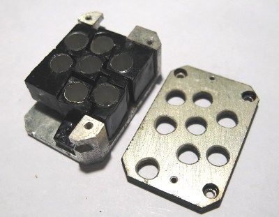
The black-coated blocks of plastic on the left (shown from the rear) act as light guides. The holes are for nesting the incandescent bulbs. Note the puzzle-like arrangement of the uniquely shaped pieces.

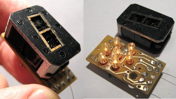
The rear of the display is a PCB with a vaguely hexagonal pattern of low-voltage incandescent bulbs, and each bulb mates to one segment of the display. The display segments themselves are solid blocks of plastic, one for each bulb, and each a separate piece. These are painted black, with the only paint-free areas being a thin segment at the top for the display, and a hole in the back for the mating bulb.

The result is that each plastic piece acts as a light guide, ensuring that a lit bulb on the PCB results in one of the seven thin segments on the face being lit as well. An interesting thing is that the black paint is the only thing preventing unwanted light from showing out the front, or leaking from one segment to another; usually some kind of baffle is used for this purpose in displays from this era.

More curiously, each plastic segment is a unique shape apparently unrelated to its function. We think this was probably done to ensure foolproof assembly; it forms a puzzle that can only fit together one way. The result is a compact and remarkably sturdy unit that shows how older and rugged tech isn’t necessarily bulky. Another example of small display tech from the Soviet era is this tiny 7-segment display of a completely different manufacture, which was usually used with an integrated bubble lens to magnify the minuscule display.

It’s A Nixie! It’s A VFD! No, It’s A Custom LED Display In A Tube

Like the look of Nixies but they just seem a little overdone? Or perhaps you just don’t want the hassles of a high-voltage power supply? Then maybe these faux-Nixie LED “tube” displays will find a way into your next clock build.

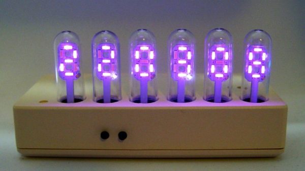
For his 2018 Hackaday Prize entry, [bobricius] decided that what the world needs is a Nixie that’s not a Nixie. To that end, each display is formed by seven surface-mount LEDs soldered to a seven-segment shaped PCB and slipped into a glass tube. The LEDs are in 4014 packages so they’re only 4 millimeters long, but what they lack in size they make up for in brightness. We’re not sure if it’s a trick of the camera, but the LEDs certainly seem to put off a bluish glow that’s reminiscent of vacuum-fluorescent displays — it’s like a Nixie and a VFD all rolled up in one package.  The current case, which hides the clock circuitry on the lower part of the PCB, is just plastic, but this would look spiffy in a fine wooden case.

Could this be another Nixie tube killer that never was? Perhaps, but wherever it ends up, we like the look of it, and we’re glad it’s one of the early Hackaday Prize entries. Have you got something to enter in the greatest hardware competition on Earth? If not, get cracking!

Careful Crafting Makes DIY 7-Segment Display Shine

[MattB] decided to go the DIY route for some 7 segment displays that were several inches tall, but he had some particular requirements. He wanted precisely shaped elements that were as cleanly and evenly lit as possible, with no obvious points of illumination from LEDs and no visibly uneven edge lighting. To do this, he used the tools and materials he had on hand and carefully handcrafted each segment. The result is awfully close to his ideal!

Continue reading “Careful Crafting Makes DIY 7-Segment Display Shine”

A Raspberry Pi Tidy Tide Tracker Predicts Propitious Promenades

The whims of the tides can make walking near the ocean a less than pleasant experience. A beautiful seascape one day may appear as a dismal, mucky, tidal flat the next. Frustrated over these weary walks, [Average Man] created a tidy tide tracker to predict propitious promenade periods.

A Raspberry Pi A+ pulls tide timing information off the web by scraping a web page using Python code. The time for the high tide, when the estuary will be full of water, is shown on a 4-digit 7-seg display. It’s all sandwiched between two smoked black panels to provide a neat case while still letting the LEDs show through.

The code comes from two projects [Average] recalled from a kickstarter timing project and a 7-seg display project. As he points out:

It’s great to learn programming from others, but it’s even better if you learn them well enough to remember, re-use and combine that code later on as well.

The display chips are mounted on a product of his own, the no longer available ProtoPal board. This is a Pi A+ size board with 288 prototyping holes and the standard connector for mounting on the Pi GPIO header. It keeps the project neat and clean.

Swollen Clock Build Demostrates All Engineering Shoulds

[Steve Gardner] wants an accurate clock for his bench. Of course the only option most engineers will accept for something like this a clock they’ve built themselves. In fact, this is his second time around as his first was an OLED based system using one of those sweet Maxim TCXO’s that keep time for years with negligible drift.

This build is going to be dead accurate as well since he plans to roll in a GPS source. But for now he’s covering the display build itself and will use another clock source IC at first. The display is a set of six 2.3″ 7-segment displays on protoboard. Bonus points for all the tidiness in his point to point soldering!

You may think this is a super simple project, and in a way it is. But [Steve] does an amazing job of dotting all the i’s and crossing all the t’s in a way that is beneficial to learn for all of your prototyping. For instance, he’s combining some 7-segment displays with 5mm LEDs as the colons. He mentions checking the peak wavelength of the displays to match the LEDs when choosing components. The design is also well-planned on graph paper. This may be just for use in illustrating the video but is a great practice in your own prototyping.

We’re not sure if there’s some movie magic involved here as his first burning of code to the PIC microcontroller results in a fully working device — impressive. Looking at his entire presentation, if you follow the workflow that [Steve] uses in his engineering, you’re doing it right!

Continue reading “Swollen Clock Build Demostrates All Engineering Shoulds”

Kitchen Timer

A Kitchen Timer Fit For MacGyver

Here’s a project that you don’t want to bring into an airport, ship through the mail, or probably even remove from your home. [ProjectGeek] has built himself a simple kitchen timer masquerading as a bomb. The build is actually pretty simple, but the end result is something that would look at home in a Hollywood action flick.

The timer circuit is built from four simple components. An 8051 microcontroller board is used as the primary controller and timer. The code is available on GitHub. This board is attached to a another board containing four momentary push buttons. These are used to program the timer and to stop the buzzing. Another board containing four 7-segment displays is used to show the remaining time on the timer. A simple piezo buzzer is used to actually alert you when the timer has run out. All of these components are connected with colorful jumper wires.

The physical part of this build is made from easily available components. Old newspapers are rolled up to form the “explosive” sticks. These are then covered in plain brown paper ordinarily used to cover text books. The rolls are bundled together and fixed with electrical tape. The electronics can then be attached to the base with some hot glue or double-sided tape.