ESP8266 Clock Puts Time In A Jar

Ironically, with the wide availability of modular electronic components today, the hardest part of constructing your latest gadget might just end up being able to find a decent looking enclosure for it. Project boxes will only get you so far, and let’s be honest, they aren’t exactly the most attractive things in the world. But if you’re willing to think outside the box (get it?) there are some unconventional options out there that might fit the bill.

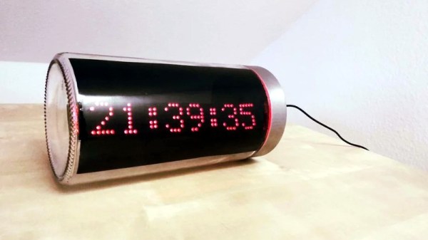
Take for example this ESP8266 clock by [ZaNgAbY] that’s housed in a glass pasta jar. With the addition of some window tint film for the LED display to shine through, the final result could nearly pass as modern art. Even if you don’t need an extra clock around the house, this same general principle could be used to create a slick-looking ticker for all sorts of information, from the weather to server uptime with just some adjustments to the code.

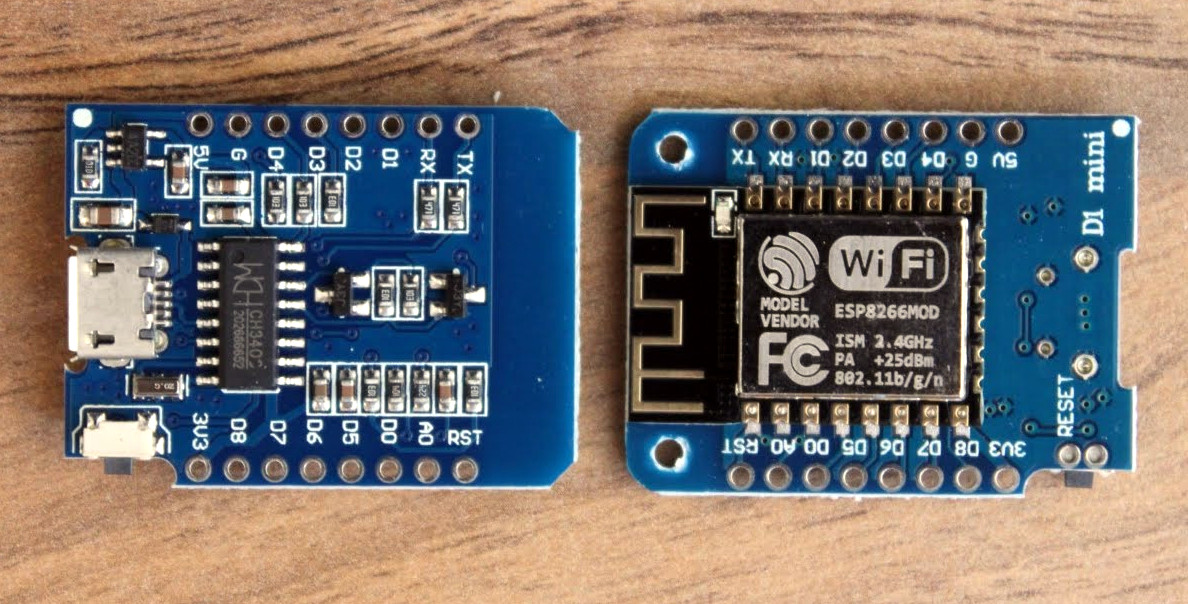
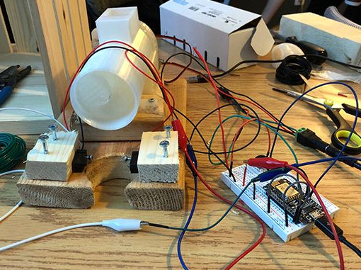
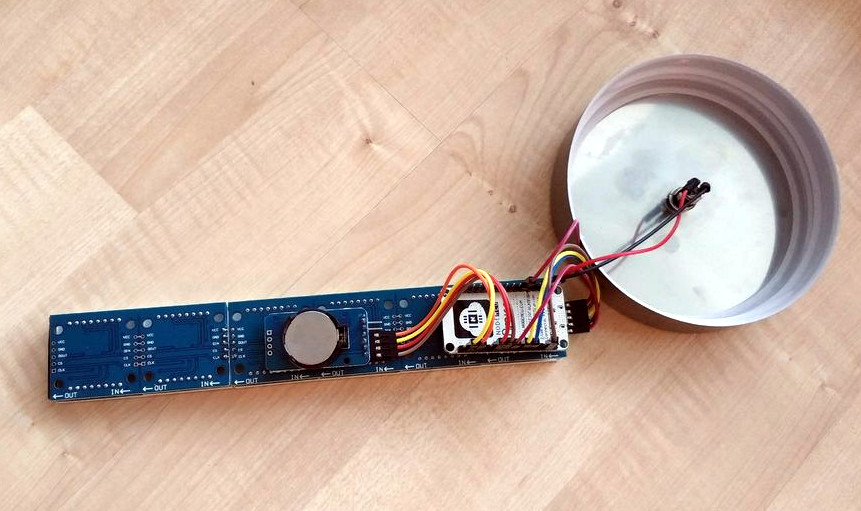
Inside the jar there’s six 8×8 MAX7219 LED matrix modules tacked together to create one long strip, with a NodeMCU board stuck to the back with double-sided tape. There’s also a DS3231 RTC module so the clock can keep halfway decent time, but depending on how aggressively you are willing to pull down the current time from NTP, that may or may not be required. A simple barrel jack is popped through the metal lid of the jar for power, and represents the only physical connection the internals have to the outside world.

For the next iteration [ZaNgAbY] is thinking of adding a temperature and humidity sensor, and a light sensor that can dim the LED display depending on the ambient light. While the environmental sensors will have to go on the outside of the lid if there’s any hope of pulling useful readings from them, the clear glass will allow him to keep the light sensor internal to the clock.

Believe it or not, this isn’t the first time we’ve seen somebody give their electronics the pickle treatment. We’ve previously played host to a server that “preserves” files in a Mason jar, as well as a gorgeous display of an iPod under glass.

Continue reading “ESP8266 Clock Puts Time In A Jar”

Easy Access Point Configuration On ESP8266

One of the biggest advantages of using the ESP8266 in your projects is how easy it is to get WiFi up and running. Just plug in the WiFi library, put the SSID and encryption key in your source code, and away you go. It authenticates with your network in seconds and you can get on with building your project. But things get a little trickier if you want to take your project someplace else, or distribute your source code to others. Quickly we learn the downside of using static variables for authentication.

While there are already a few solutions to this problem out there, [Martin Raynsford] wasn’t too thrilled with them. Usually they put the ESP8266 in Access Point mode, allow the user to connect, and then ask which network they should authenticate with. But he didn’t want his projects to require an existing network, and figured he could do just as well making a field-configurable AP.

Using it is simple. Once the ESP8266 starts up it will create a new network in the form of “APConfig XXXXXX”, which should be easy enough to find from your client side device. Once connected, you can go to a simple administration page which allows you to configure a new AP name and encryption key. You even have the option to create an open AP by leaving the “Password” field blank. Once rebooted, the ESP8266 will create a new network with the defined parameters.

[Martin] has also included a “backdoor” to let anyone with physical access to the ESP8266 board create a new open AP that can be used to reconfigure the network settings. During boot up there is a brief period, indicated with specific blinks of the LED, wherein you can hit the reset button and trigger the open AP. This keeps you from getting locked out of your own project if you forget what key you gave it.

If you’re not one to go the austere route, take a look at some of the more robust solutions we’ve seen for easier end-user setup of the ESP8266.

WebSockets Embedded With The ESP8266

It used to be that Web browsing was simple. You asked a server for some text, which was duly sent, and then formatted by your browser. Now a web page is as likely to be a full-blown application that is reading mail, editing text, or lots of other things and may use WebSockets to create a back channel to the server. Thanks to affordable hardware like the ESP8266 one of those things a modern web browser can do is sense and control the real world. [Acrobotic] has an interesting video about using WebSockets to allow a browser to talk to an ESP8266 web server in real time. You can see his simple demo in the video below.

Of course, you’ll use the usual language you use on the ESP8266 — [Acrobotic] uses C++ in the Arduino IDE. On the browser side you’ll use JavaScript, although that will be embedded in your C++ program which acts as a web server.

Continue reading “WebSockets Embedded With The ESP8266”

Seeed Air602 WiFi dev board.

Tiny WiFi-Enabled ARM MCU For Tiny Projects

Ever since the ESP8266 WiFi-enabled microcontroller came on the scene, it seemed like suddenly everyone came up with WiFi-enabled projects. But the ESP8266 is not the only game in town! Reader [PuceBaboon] notified us of a new product released by Seeed Studios: the imaginatively called Air602 WiFi Development Board.

The core of this board is the tiny WinnerMicro W600 MCU, which integrates a 32-bit ARM Cortex M3 CPU, along with dual UARTs, I2C, SPI and I2S interfaces, as well as a real-time clock (RTC). Add to this hardware crypto, seven I/O pins (five broken out on the development board) and you have a very capable WiFi-enabled MCU which can be programmed using the usual ARM development tools (e.g. Keil) using the provided SDK.

The W600 module can be bought by itself, in all its diminutive 12 mm x 10 mm glory, for a mere $1.90 as of time of writing – without antenna – as noted in [PuceBaboon]’s thoughts on this MCU and the development board.

Drill Jig Helps Mount WeMos D1 Mini

As far as ESP8266 boards go, the WeMos D1 Mini is a great choice if you’re looking to get started with hackerdom’s microcontroller du jour. It’s small, well supported, and can be had ridiculously cheap. Often going for as little as $3 USD each, we buy the things in bulk just to have spares on hand. But that’s not to say it’s a perfect board. For one, it lacks the customary mounting holes which would allow you to better integrate it into finished products.

This minor annoyance was enough to spring [Martin Raynsford] into action. He noticed there was some open area on the D1 Mini’s PCB where it seemed he could drill through to add his own mount points, but of course popping holes in a modern PCB can be risky business. There’s not a lot of wiggle room between success and heartbreak, and it’s not like the diminutive D1 Mini is that easy to hold down to begin with. So he designed a laser-cut jig to allow him to rapidly add mounting holes to his D1 Mini’s assembly line style.

For those who might be skeptical, [Martin] reports he’s seen no adverse effects from drilling through the board, though does admit it’s possible the close proximity of the metal screw heads to the ESP8266’s antenna may have a detrimental effect. That said, he’s tested them in his projects out to 25 m (82 feet) with no obvious problems. He’s using a 2 mm drill bit to make his hole, and M2 x 6 mm machine screws to hold the boards down.

The jig design is released as a SVG and DXF for anyone with a laser cutter to replicate, but it shouldn’t be too difficult to extrude those designs in the Z dimension for hackers who haven’t yet jumped on the subtractive manufacturing bandwagon.

When a project makes the leap from prototype to in-house production, designing and building jigs become an essential skill. From flashing firmware to doing final checkout, the time and effort spent building a jig early on will pay for itself quickly in production.

RTL-SDR Paves Way To Alexa Controlled Blinds

You’d be forgiven for occasionally looking at a project, especially one that involves reverse engineering an unknown communication protocol, and thinking it might be out of your league. We’ve all been there. But as more and more of the devices that we use are becoming wireless black boxes, we’re all going to have to get a bit more comfortable with jumping into the deep end from time to time. Luckily, there are no shortage of success stories out there that we can look at for inspiration.

A case in point are the wireless blinds that [Stuart Hinson] decided would be a lot more useful if he could control them with his Amazon Alexa. There’s plenty of documentation on how to get Alexa to do your bidding, so he wasn’t worried about that. The tricky part was commanding the wireless blinds, as all he had to go on was the frequency printed on the back of the remote.

Luckily, in the era of cheap RTL-SDR devices, that’s often all you need. [Stuart] plugged in his receiver and fired up the incredibly handy Universal Radio Hacker. Since he knew the frequency, it was just a matter of tuning in and hitting the button on the remote a couple times to get a good capture. The software then broke it down to the binary sequence the remote was sending out.

Now here’s where [Stuart] lucked out. The manufacturers took the easy way out and didn’t include any sort of security features, or even bother with acknowledging that the signal had been received. All he needed to do was parrot out the binary sequence with a standard 433MHz transmitter hooked up to an ESP8266, and the blinds took the bait. This does mean that anyone close enough can take control of these particular blinds, but that’s a story for another time.

We took a look at the Universal Radio Hacker a year or so back, and it’s good to see it picking up steam. We’ve also covered the ins and outs of creating your own Alexa skills, if you want to get a jump on that side of the project.

Feeding Dogs Over Twitch Is Latest E-Sport Craze

The modern social-networking fueled Internet loves two things more than anything: pets, and watching other people do stuff. There’s probably a scroll tucked behind a filing cabinet at Vint Cerf’s house that foretells anyone who can harness these two elements will gain control of the Internet Ready Player One style. If so, we’re thinking [Tyler Pearce] is well on his way to ascending the throne.

In an effort to make the Overwatch Twitch streams of his betrothed even more enticing, [Tyler] came up with a way for viewers to feed their dog Larry by dropping a command in the chat. There’s a surprisingly complex dance of software and hardware to make this reliable and visually appealing, but it’s worth it as showmanship is important in the brave new world of competitive e-sports. We’re assuming that’s what it says in the issue of ESPN Magazine with the Fortnite player on the cover, but nobody at Hackaday would qualify for a subscription to it so we don’t really know for sure.

A server running on the computer provides a slick administrative dashboard for the treat system, including a running log of who fed Larry and when. There’s also a number of checks in place to prevent too many treats being dispensed in a short time period, and to keep an individual from spamming the system.

On the hardware side, he’s using two NodeMCU ESP8266 microcontollers connected to a local MQTT broker: one to handle the lighting and one to run the 3D printed auger that actually pushes the food out. The printed auger is powered by a standard hobby servo, and even includes an IR sensor to automatically stop spinning when it detects a treat has been dispensed. [Tyler] reports the auger works quite well, though does have a tendency to jam up if overfilled.

We’ve seen all manner of automated pet feeders over the years, even ones with their own email accounts. So it was probably only a matter of time until they came to Twitch. If you can install Linux with it, why not use it to feed your dog? Or somebody else’s, as the case may be.