Remember learning all about functions in algebra? Neither do we. Oh sure, most of us remember linear plots and the magic of understanding y=mx+b for the first time. But a lot of us managed to slide by with only a tenuous grasp of more complex functions like exponentials and conic sections. Luckily the functionally challenged among us can bolster their understanding with this demonstration using analog multipliers and op amps.
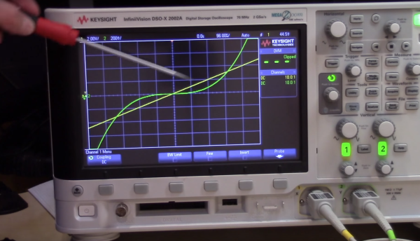
[devttys0]’s video tutorial is a great primer on analog multipliers and their many uses. Starting with a simple example that multiplies two input voltages together, he goes on to show circuits that output both the square and the cube of an input voltage. Seeing the output waveform of the cube of a ramped input voltage was what nailed the concept for us and transported us back to those seemingly wasted hours in algebra class many years ago. Further refinements by the addition of an op amp yield a circuit that outputs the square root of an input voltage, and eventually lead to a voltage controlled resistor that can attenuate an input signal depending on its voltage. Pretty powerful stuff for just a few chips.
The chip behind [devttys0]’s primer is the Analog Devices AD633, a pretty handy chip to have around. For more on this chip, check out [Bil Herd]’s post on analog computing.
Continue reading “Make Math Real With This Analog Multiplier Primer”