Nixie Clock Without A PCB

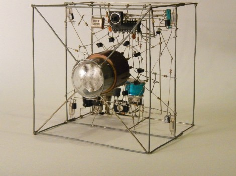
Looking for an artistic way to build circuits? Don’t want to design a PCB? The Lethal Nixie Tube Clock is a free form circuit that gives you the time one digit at a time. It uses a IN-1 Nixie tube to display the digits. This is driven by ten MPSA42 high voltage transistors. A IRF520 N-FET, inductor, and a diode are used as a switching power supply that generates the high voltage needed to drive the Nixie tube. It’s probably not lethal, but there are exposed high voltages in the cube. You’d definitely regret touching it.

An ATMega8 is used to control the clock. It drives the various digits of the Nixie tube, and generates a PWM output to switch the high voltage supply. Unfortunately, the schematic has been lost. If you’re interested in the switching supply, it’s likely similar to the one explained here.

Check out a video of the clock after the break.

Via Dangerous Prototypes

Continue reading “Nixie Clock Without A PCB”

Controlling Your Webcam With An Old Guitar Hero Pedal

Hackaday reader [Tom Price] often uses Skype to communicate with family near and far, but he was getting tired of adjusting his webcam each time his kids moved out of frame. While the solution he came up with isn’t fully automated, it is hands-free, which is good enough for his purposes.

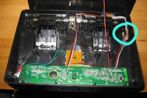
[Tom] was looking around for an electronic foot pedal of some sort when he came across a wireless 3rd party Guitar Hero peripheral that happened to fit the bill. Using an Arduino library created by [Bill Porter], he was quickly able to get the toy to communicate with an Arduino-flashed Atmega8, but things kind of fell flat when it came time to relay signals back to his computer. Using another Atmega8 along with the PS2X library, he was able to emulate the Guitar Hero controller that his foot pedal was looking for.

With the pedal portion of his project wrapped up, he focused on his webcam. [Tom] mounted the camera on a small servo, which he then wired up to the receiving end of his foot pedal rig. As you can see in the video below, he can now pan his camera across the room with a tap of his foot, rather than leaning in and manually adjusting it.

Continue reading “Controlling Your Webcam With An Old Guitar Hero Pedal”

Use Your TV Remote As An HID Mouse

[Vinod’s] latest project lets him use a TV remote control as a mouse. It may not sound like much, but he did it with a minimum of hardware and packed in the maximum when it comes to features.

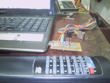
He’s using an ATmega8 to read the remote control signals and provide USB connectivity. With the V-USB stack he enumerates the device as an HID mouse. One note of warning, he used the PID/VID pair from the USBasp programmer project. If you use that programmer you’ll need to uninstall the drivers to get this to work (we think this is only necessary on a Windows box).

The cursor can be moved in eight directions using the number pad on the remote. The numeral five falls in the center of the directional buttons so [Vinod] mapped that to the left click, with the zero key serving as right click. He even included the scroll wheel by using the volume buttons. The firmware supports cursor acceleration. If you hold one direction the cursor will move slowly at first,then pick up speed. Fine adjustments can be made by single clicking the button. Check out his demonstration embedded after the break.

Continue reading “Use Your TV Remote As An HID Mouse”

VGA Message Board Displays SMS Without A Computer

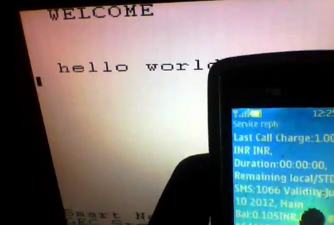
[Achu Wilson’s] latest creation is a VGA message board which is written to via SMS text messages. This doesn’t sound too interesting at first, until you find out he’s doing this with a microcontroller rather than a PC. All of the complexity is in the code that drives the VGA. He managed to do it without any jitter while using an 8-bit microcontroller.

But first, the cellular side of things. A GSM modem takes care of connectivity. To communicate with the modem [Achu] used an ATmega8. He mentions the he could have used a much smaller uC, like an ATtiny, but this is what he had lying around. When a message is received the ATmega8 feeds the characters to an ATmega16 which is driving the VGA monitor. Rather than deal with the analog voltages necessary to run a color display he simply ganged the three color lines together and drives them from one of the microcontroller pins. This results in white and black which correspond to voltage or no voltage.

You can see him showing off the system in the clip after the break.

Continue reading “VGA Message Board Displays SMS Without A Computer”

Morse Code Interpreter

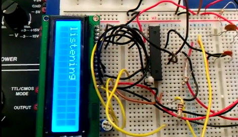
[Sulaiman Habsi] and two classmates put together a Morse Code interpreter as a class project at Sultan Qaboos University. The system listens to a morse code signal using a microphone, then translates that input to text which is displayed on this character LCD.

The breadboarded circuit feeds an audio signal from the microphone, through an OpAmp, to the ADC of an ATmega8 microcontroller. The captured signal is stored as a byte in a special way. The three least-significant bits signify how many total dots or dashes are contained in the character, the remaining bits represent those dots and dashes with zeros and ones. A full description of this process is included in a PDF linked in the article above. As you can see in the video after the break, the hardware waits to process all of the signals once the full message has been received.

This would be a great add-on for a Morse Code practice keyer.

Continue reading “Morse Code Interpreter”

Build Your Own 4-channel Logic Analyzer

If you’re just getting into hobby electronics chances are there are lots of tools you’d like to get you hands on but can’t yet justify the purchases. Why not build some of the simpler ones? Here’s a great example of a 4-channel logic analyzer that can be your next project and will add to your arsenal for future endeavors.

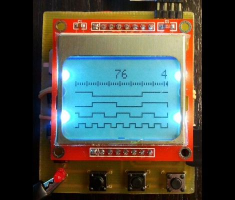
As you can see, [Vassilis’] creation uses a cellphone-sized LCD screen as the output. It is powered by four rechargeable batteries and driven by an ATmega8 microcontroller. He’s designed the tool without power regulation, relying on the ATmega’s rather wide range of operating voltages, and a few diodes to step down that voltage for the LCD screen.

As you can see in the clip after the break, alligator leads can be used to connect the test circuit to the inputs (don’t forget the ground reference!). Thee buttons at the bottom let you navigate the captured data by panning and zooming. Perhaps the best design feature is the single-sided circuit board which should be quite easy to reproduce at home.

Continue reading “Build Your Own 4-channel Logic Analyzer”

Build An Intervalometer With These Simple Fabrication Techniques

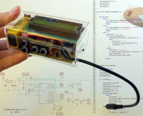
[L] just finished building this intervalometer and his verbose documentation of the project has a little bit of everything. The fabrication uses common prototyping materials, and simple skills that are easy to master even for the beginner.

The hardware is based around an ATmega8 microcontroller. After snooping around the Internet [L] wanted to see if the voltage divider based focus and shutter commands that are present in some camera remote shutter controls would work for his model. Investigation with a commercial shutter release showed him how it was done, so he incorporated that into his design. When it comes to firmware for the device we really like his explanation of the menu system. There’s a lot of settings and he did a great job of planning the user interface to make them all work on the finished product.

The schematic and board layout were done with Eagle. During the layout process he made choices for easy assembly using strip board, and even walks us through the steps when cutting the traces and adding jumper wires. It’s nicely finished in this clear plastic case and demonstrated in the video after the break.

Continue reading “Build An Intervalometer With These Simple Fabrication Techniques”