A Simple, DIY GPS Tracker

Today, there are dozens of off-the-shelf solutions for a GPS tracking device. Most of them use GSM, some of them use satellites, and all of them are astonishingly inexpensive. If you want to track a car, dog, or your luggage, you’ve never had more options.

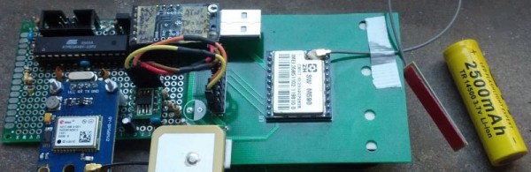
[Emilio] wanted to track his own car, and the original solution for this was a smartphone. This smartphone was also a good choice, as it’s a programmable GPS device connected to a cell network, but there had to be a simpler solution. It came in the form of an eight euro GPS module and a three euro GSM module (Google Translatrix right here). The rest of the hardware is an ATMega48V [Emilio] had sitting around and a 2500 mAh lithium cell. It’s a cellular tracker make out of eleven euro’s worth of hardware and some junk in a drawer.

There are only a few caveats to this hardware. First, the ATmega48V only has one UART. This is connected to the GPS module at 9600, 8N1. The connection to the GSM M-590 module is only 2400 bps, and slow enough for a bitbanged UART. This hardware is soldered to a piece of perfboard, thus ending the hardware part of this build.

The software is a little more complex, but not by very much. The GPS part of the firmware records the current latitude and longitude. If the GSM module receives a call, it replies with an SMS of the current GPS coordinates and a few GPS coordinates seen earlier. Of course, a pre-paid SIM is required for this build, but those are cheap enough.

Not even ten years ago, a simple, DIY GPS tracker would have cost a small fortune. Now that we have cheap GPS modules, GSM modules, and more magical electronics from the East, builds like this are easy and cheap. What a magical time to be alive.

OBDII to Speed Pulse: Atmel ICE

Building An OBD Speed Pulse: Behold The ICE

I am a crappy software coder when it comes down to it. I didn’t pay attention when everything went object oriented and my roots were always assembly language and Real Time Operating Systems (RTOS) anyways.

So it only natural that I would reach for a true In-Circuit-Emulator (ICE) to finish of my little OBDII bus to speed pulse generator widget. ICE is a hardware device used to debug embedded systems. It communicates with the microcontroller on your board, allowing you to view what is going on by pausing execution and inspecting or changing values in the hardware registers. If you want to be great at embedded development you need to be great at using in-circuit emulation.

Not only do I get to watch my mistakes in near real time, I get to make a video about it.

Getting Data Out of a Vehicle

I’ve been working on a small board which will plug into my car and give direct access to speed reported on the Controller Area Network (CAN bus).

To back up a bit, my last video post was about my inane desire to make a small assembly that could plug into the OBDII port on my truck and create a series of pulses representing the speed of the vehicle for my GPS to function much more accurately. While there was a wire buried deep in the multiple bundles of wires connected to the vehicle’s Engine Control Module, I have decided for numerous reasons to create my own signal source.

At the heart of my project is the need to convert the OBDII port and the underlying CAN protocol to a simple variable representing the speed, and to then covert that value to a pulse stream where the frequency varied based on speed. The OBDII/CAN Protocol is handled by the STN1110 chip and converted to ASCII, and I am using an ATmega328 like found on a multitude of Arduino’ish boards for the ASCII to pulse conversion. I’m using hardware interrupts to control the signal output for rock-solid, jitter-free timing.

Walk through the process of using an In-Circuit Emulator in the video below, and join me after the break for a few more details on the process.

Continue reading “Building An OBD Speed Pulse: Behold The ICE”

DIY Tiny Single-PCB Synthesizer

[Jan Ostman] has been pushing the limits of sound synthesis on the lowly AVR ATMega microcontrollers, and his latest two project is so cute that we just had to write it up. The miniTS shares the same basic sound-generation firmware with his previous TinyTS, which we’ve covered here before, but adds a lot more keys, an OLED, and MIDI, while taking away some of the knobs.

Both feature keyboards that are just copper pads placed over a ground plane, and the code does simple capacitive-sensing to figure out if they’re being touched or not. The point here is that you could pick up a PCB from [Jan] on the cheap, and experiment around with the code. Or you could just take the code and make a less refined version for yourself with a cheapo Arduino and some copper plates.

Either way, we like the combination of minimal materials and maximum tweakability, and think it’s cool that [Jan] shares the code, if not also the PCB designs. Anyone with PCB layout practice could get a clone worked up in an afternoon, although it’s going to be cheaper to get these made in bulk, and you’re probably better off just buying one from [Jan].

Boost Converter Functionality At Rock-Bottom Prices

Linear voltage regulators are pretty easy to throw into a project if something in it needs a specific voltage that’s lower than the supply. If it needs a higher voltage, it’s almost just as easy to grab a boost converter of some sort to satisfy the power requirements. But if you’re on a mission to save some money for a large production run, or you just like the challenge of building something as simply as possible, there are ways of getting voltages greater than the supply voltage without using anything as non-minimalistic as a boost converter. [Josh] shows us exactly how this can be done using a circuit known as a charge pump to drive a blue LED.

One of the cool things about AVR microcontrollers is that they can run easily on a coin cell battery and source enough current to drive LEDs directly from the output pins. Obviously enough, if the LED voltage is greater than the voltage of the power supply, this won’t work. That is, unless you have a spare diode and capacitor around to build a charge pump.

The negative charge pump works by charging up a capacitor that is connected to an AVR pin, with the other side between the LED and a garden-variety diode to ground. That results in a roughly (VCC – 0.7) volt difference across the capacitor’s plates. When the AVR pin goes low, the other side of the capacitor goes negative by this same amount, and this makes the voltage across the LED high enough to light up. Not only is this simpler than a boost converter, but it doesn’t need any bulky inductors to work properly.

Will this work for any load? Am I going to start any fires by overdriving the LED? Luckily, [josh] answers all of these questions and more on the project page, and goes into some detail on the circuit theory as well. Granted, the charge pump doesn’t have the fine control over the power supply that you can get out of a buck or boost converter (or any switch-mode power supply). But it does have good bang-for-the-buck.

Does This Demo Remind You Of Mario Kart? It Should!

Here’s a slick-looking VGA demo written in assembly by [Yianni Kostaris]; it’s VGA output from an otherwise stock ATmega2560 at 16MHz with no external chips involved. If you’re getting some Super Mario Kart vibes from how it looks, there’s a good reason for that. The demo implements a form of the Super Nintendo’s Mode 7 graphics, which allowed for a background to be efficiently texture-mapped, rotated, and scaled for a 3D effect. It was used in racing games (such as Super Mario Kart) but also in many others. A video of the demo is embedded below.

[Yianni] posted the original demo a year earlier, but just recently added detailed technical information on how it was all accomplished. The AVR outputs VGA signals directly, resulting in 100×120 resolution with 256 colors, zipping along at 60 fps. The AVR itself is not modified or overclocked in any way — it runs at an entirely normal 16MHz and spends 93% of its time handling interrupts. Despite sharing details for how this is done, [Yianni] hasn’t released any code, but told us this demo is an offshoot from another project that is still in progress. It’s worth staying tuned because it’s clear [Yianni] knows his stuff.

Continue reading “Does This Demo Remind You Of Mario Kart? It Should!”

Portable Apple II On An AVR

The Apple II was one of the first home computers. Designed by Steve “Woz” Wozniak, it used the MOS technologies 6502 processor, an 8-bit processor running at about 1 MHz. [Maxstaunch] wrote his bachelor thesis about emulating the 6502 in software on an AVR1284 and came up with a handheld prototype Apple II with screen and keyboard.

pic_15
Prototype on veroboard

Originally, [maxstrauch] wanted to build an NES, which uses the same 6502 processor, but he calculated the NES’s Picture Processing Unit would be too complicated for the AVR, so he started on emulating the Apple II instead. It’s not quite there – it can only reference 12K of memory instead of the 64K on the original, so hi-res graphic mode, and therefore, many games, won’t work, but lo-res mode works as well as BASIC (both Integer BASIC and Applesoft BASIC.)

[Maxstrauch] details the 6502 in his thesis and, in a separate document, he gives an overview of the project. A third document has the schematic he used to build his emulator. His thesis goes into great detail about the 6502 and how he maps it to the AVR microcontroller. The build itself is pretty impressive, too. Done on veroboard, the build has a display, keyboard and a small speaker as well as a micro SD card for reading and storing data. For more 6502 projects, check out the Dis-Integrated 6502 and also, this guide to building a homebrew 6502.

Continue reading “Portable Apple II On An AVR”

MicroLisp With Matching Parens

Lisp is a supremely elegant programming language, but you won’t find it around much today. That’s a shame; in the 80s and 90s, all the cool kids were using Lisp machines, computers dedicated to the creation and interpretation of Lisp. While the AI renaissance of the 80s is dead, replaced with the machine learning fad of today, Lisp machines have gotten much smaller. Now, they’ll fit in your pocket, and they have parenthesis matching, to boot.

If this build looks familiar, you’re not wrong. A while back, we saw a similar pocket Lisp computer based around the ATMega328 microcontroller with 32k of Flash and 2k of RAM. That’s not a lot by any measure, and a much more suitable processor for an AVR-based pocket Lisp machine would be the big boys of the ATMega family.

The new and improved version of the Tiny Lisp Computer is built around the ATMega1284. If it’s capable enough to run a 3D printer, it should run Lisp very well. With more program space and more RAM come more features including matching parens when entering code, a serial monitor interface, and a program editor – basically a text editor on the chip.

Apart from the larger chip, the circuit remains relatively unchanged. The display is still an OLED that can be had for a few dollars from the usual online retailers, and the other bits of circuitry are still just a handful of resistors, caps, and wire. An off-the-shelf FTDI module (or whatever serial chip you desire) can be added to connect to a serial terminal, and support for a PS/2 keyboard rounds out the board.