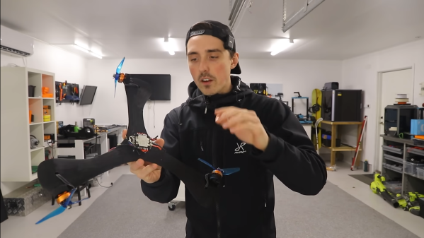
Boomerangs are known for their unique ability to circle back to the thrower, but what if you could harness this characteristic for powered for free flight? In a project that spins the traditional in a new direction, [RCLifeOn] electrifies a boomerang to make it fly laps.
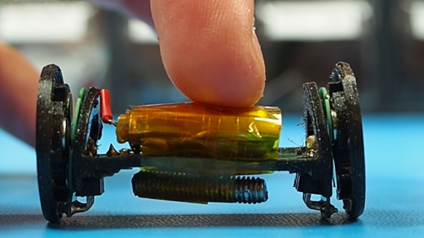
The project started with several of the 3D printed boomerang designs floating around on the internet, and adding motor mounts to the tips. [RCLifeOn] is no stranger to RC adventures, and his stockpile of spare parts from previous flying and floating projects proved invaluable. He added motor mounts and mounted all the electronics, including a RC receiver for controlling the throttle, but first iteration didn’t have enough lift, so the boomerang and motors were scaled up.
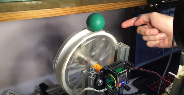
[RCLifeOn] launched the contraptions by letting them spin on the end of a stick until they achieve lift-off. The second iteration still couldn’t quite get into the air, but after increasing the blade angles using a heat gun it was flying laps around the field.
Although we’ve seen spinning drones that are controllable, it would be no small control systems challenge to make it completely RC controlled. In the meantime this project is a fun, if somewhat risky way to mix the traditional with modern tech.