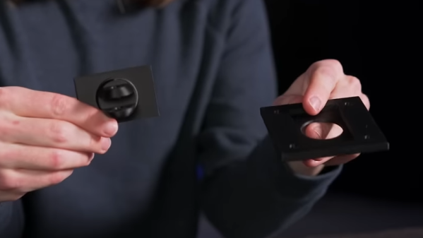
[Jeremy Weatherford] clearly has a knack for explaining projects well enough for easy reproduction but goes way further than most and has created a four-part YouTube series detailing every step from project inception to the final assembly, covering all aspects of 3D modelling and PCB design for a custom MacroPad design. Many tools are introduced along the way, all of which help reduce complexity and, by extension, the scope for errors. As every beginner hacker knows, early successes breed confidence and make for better and more ambitious projects.
Part 1 covers the project motivation and scope and introduces a keyboard layout editor tool. This tool allows one to take a layout idea and generate a JSON file, which is then used to drive keyboard tools. XYZ to produce a usable KiCAD project. The tool only generates a PCB project and an associated netlist file. No schematic is created; you don’t need one for a simple layout.
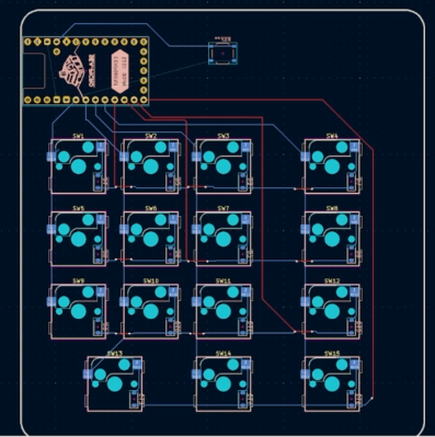
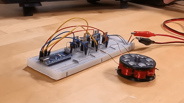
Part 2 is a walkthrough of the design process in KiCAD, culminating in ordering the PCB from JLCPCB and assembling the surface-mount parts. This particular design uses a controller based on the Sea-Picro RP2040 module, but there are many options if you have other preferences. [Jeremy] shows what’s possible with the selected suppliers, but you need not follow this step precisely if you have other ideas or want to use someone local.
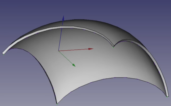
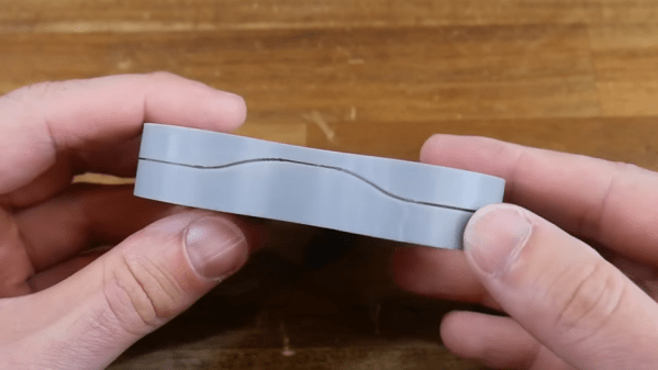
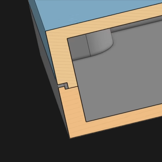
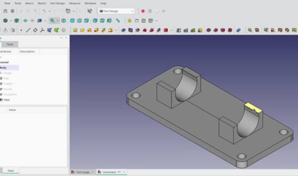
Part 3 covers exporting the mechanical aspects of the PCB out of KiCAD and into a 3D CAD program, specifically OnShape. [Jeremy] covers some crucial details, such as how to read the mechanical drawing of the keys to work out where to place the top plate. It’s very easy to plough straight in at this stage and make a design which cannot be assembled! The plan is to use a simple laser-cut box with a bottom plate with mounting holes lining up with those on the PCB. A Top plate is created by taking the outline of the PCB and adding a little margin. An array of rectangular cutouts are designed for the keys to protrude, lining up perfectly with where the keys would be when mounted on the PCB below. The sides of the case are formed from laser-cut sections that lock into each other and the laser-cut base—using the laser joint feature-script addon tool from the OnShape community channel. A second feature script addon is used to auto-layout the laser-cut components onto a single sheet. A CAM application called Kiri Moto is used to export for laser cutting and is available on the OnShape store.