The border between consumer electronics and DIY projects is getting harder and harder to define. First it was PCBs, which quickly went from homemade to professional with quick-turn services. Then low-cost CAD/CAM packages and high-end fabrication services gave us access to enclosures that were more than black plastic boxes with aluminum covers. Where will it end?
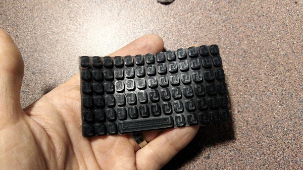
That’s a question [arturo182] begins to answer with this custom-molded silicone keyboard for a handheld device. There’s no formal writeup, but the Twitter thread goes into some detail about the process he used to make the tiny qwerty keypad. The build started by milling a two-part mold from acrylic. Silicone rubber was tinted and degassed before injecting into the mold with a baster. The keys are connected by a thin membrane of silicone, and each has a small nub on the back for actuating a switch.
There’s clearly room for improvement in this proof of concept – tool marks from the milling process mar the finish of the keys slightly, for instance. There may be tips to be had from this article on silicone keyboard refurbishment to improve the process, but overall, we’d say [arturo182] is well on his way here.