If you’re building a smart watch these days (yawn!), you’ve got to have some special sauce to impress the jaded Hackaday community. [Dominic]’s NeoPixel SmartWatch delivers, with his own take on what’s important to have on your wrist, and just as importantly, what isn’t.
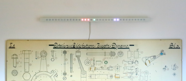
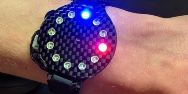
 There’s no fancy screen. Instead, the watch gets by with a ring of NeoPixels for all its notification needs. But notification is what it does right. It tells [Dominic] when he’s got an incoming call of course, but also has different flashing color modes for SMS, Snapchat, and e-mail. Oh yeah, and it tells time and even has a flashlight mode. Great functionality for a minimalistic display.
But that’s not all! It’s also got a light sensor that works from the UV all the way down to IR. At the moment, it’s being used to automatically adjust the LED brightness and to display current UV levels. (We imagine turning this into a sunburn alarm mode.) Also planned is a TV-B-Gone style IR transmitter.
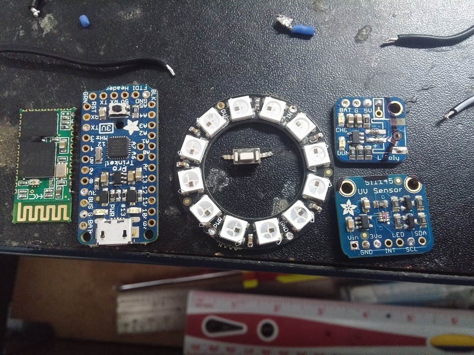
The hardware is the tough part of this build, and [Dominic] ended up using a custom PCB to help in cramming so many off-the-shelf modules into a tiny space. Making it look good is icing on the cake.
Thanks [Marcello] for the tip!
Continue reading “The Smartest Smart Watch Is The One You Make Yourself”
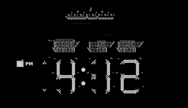
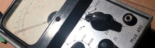
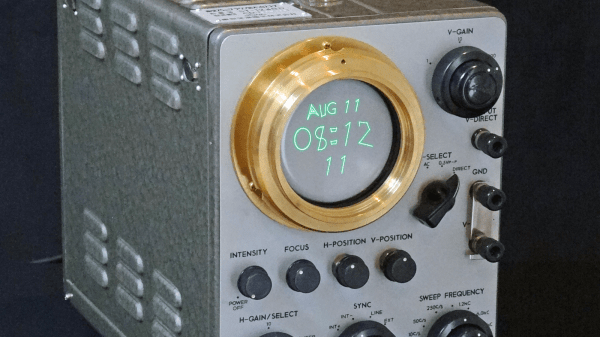
 Strictly speaking, [Giulio Pons]’s clock project isn’t new at all. He’s taken a broken multimeter from the 1950s, and with the help of an Arduino Nano and an ESP8266 module,