Crystal Oscillators Explained

We’ve read a lot about oscillators, but crystal oscillators seem to be a bit of a mystery. Hobby-level books tend to say, build a circuit like this and then mess with it until it oscillates. Engineering texts tend to go on about loop gains but aren’t very clear about practice. A [circuit digest] post that continues a series on oscillators has a good, practical treatment of the subject.

Crystals are made to have a natural resonant frequency and will oscillate at that frequency or a multiple thereof with the proper excitation. The trick, of course, is finding the proper excitation.

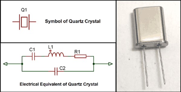
The post starts with a basic model of a crystal having a series capacitance and inductance along with a resistance. There’s also a shunt or parallel capacitor. When you order a crystal, you specify if you want the resonant frequency in series or parallel mode — that is, which of the capacitors in the model you want to resonate with the inductor — so the model has actual practical application.

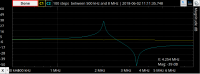
By applying the usual formula for resonance on the model you’ll see there is a null and a peak which corresponds to the two resonance points. The dip is the series frequency and the peak is the parallel. You can actually see a trace for a real crystal in a recent post we did on the Analog Discovery 2. It matches the math pretty well, as you can see on the right.

Continue reading “Crystal Oscillators Explained”

The Crystal (Testing) Method

It used to be any good electronics experimenter had a bag full of crystals because you never knew what frequency you might need. These days, you are likely to have far fewer because you usually just need one reference frequency and derive all the other frequencies from it. But how can you test a crystal? As [Mousa] points out in a recent video, you can’t test it with a multimeter.

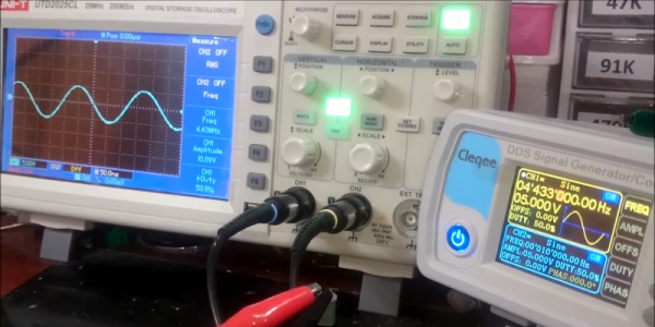
His approach is simple: Monitor a function generator with an oscilloscope, but put the crystal under test in series. Then you move the frequency along until you see the voltage on the oscilloscope peak. That frequency should match the crystal’s operating frequency.

Continue reading “The Crystal (Testing) Method”

Transistor Logic Clock Gets Stacked Up

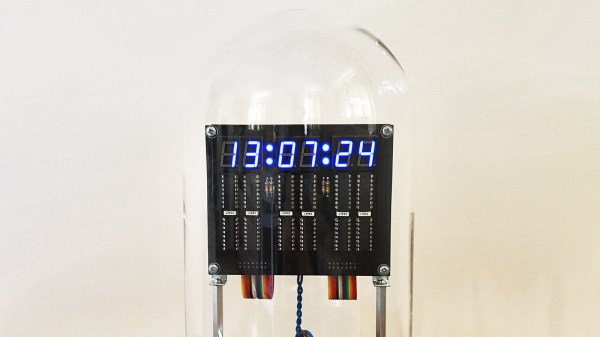
A couple years back we covered a very impressive transistor logic clock which was laid out so an observer could watch all of the counters doing their thing, complete with gratuitous blinkenlights. It had 777 transistors on 41 perfboards, and exactly zero crystals: the clock signal was extracted from the mains frequency of 50 Hz. It was obviously a labor of love and certainly looked impressive, but it wasn’t exactly the most practical timepiece we’d ever seen.

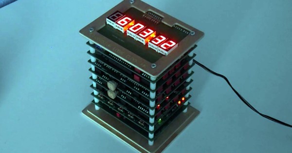
Creator [B Brett] recently wrote in to share news that the second version of his transistor logic clock has been completed, and we can confidently say it’s a triumph. He’s dropped the 41 perfboards in favor of 9 professionally fabricated PCBs, which this time around are stacked vertically to make it a bit more desktop friendly. The end goal of a transistor logic clock that you can take apart to study is the same, but this “MkII” as he calls it is a far more refined version of the concept.

In addition to using fewer boards, the new MkII design cuts the logic down to only 283 transistors. This is thanks in part to the fact that he allowed himself the luxury of including an oscillator this time. The clock uses a standard watch crystal at 32.768 KHz, the output of which is converted into a square wave through a Schmitt trigger. This is then fed into a divider higher up the stack which uses flip flops to produce 1Hz and 2Hz signals for use throughout the rest of the clock.

In addition to the original version of this project, we’ve also seen a beautiful single-board wall mounted version, and even a “dead bug” style one built from scraps.

Continue reading “Transistor Logic Clock Gets Stacked Up”

Classifying Crystals With An SDR Dongle

When it comes to radio frequency oscillators, crystal controlled is the way to go when you want frequency precision. But not every slab of quartz in a tiny silver case is created equal, so crystals need to be characterized before using them. That’s generally a job for an oscilloscope, but if you’re clever, an SDR dongle can make a dandy crystal checker too.

The back story on [OM0ET]’s little hack is interesting, and one we hope to follow up on. The Slovakian ham is building what looks to be a pretty sophisticated homebrew single-sideband transceiver for the HF bands. Needed for such a rig are good intermediate frequency (IF) filters, which require matched sets of crystals. He wanted a quick and easy way to go through his collection of crystals and get a precise reading of the resonant frequency, so he turned to his cheap little RTL-SDR dongle. Plugged into a PC with SDRSharp running, the dongle’s antenna input is connected to the output of a simple one-transistor crystal oscillator. No schematics are given, but a look at the layout in the video below suggests it’s just a Colpitts oscillator. With the crystal under test plugged in, the oscillator produces a huge spike on the SDRSharp spectrum analyzer display, and [OM0ET] can quickly determine the center frequency. We’d suggest an attenuator to change the clipped plateau into a sharper peak, but other than that it worked like a charm, and he even found a few dud crystals with it.

Fascinated by the electromechanics of quartz crystals? We are too, which is why [Jenny]’s crystal oscillator primer is a good first stop for the curious.

Continue reading “Classifying Crystals With An SDR Dongle”

Drifting Instrument Presents Opportunity To Learn About Crystal Oscillators

Sure, we all love fixing stuff, but there’s often a fine line between something that’s worth repairing and something that’s cheaper in the long run to just replace. That line gets blurred, though, when there’s something to be learned from a repair.

This wonky temperature-compensated crystal oscillator is a good example of leaning toward repair just for the opportunity to peek inside. [Kerry Wong] identified it as the problem behind a programmable frequency counter reading significantly low. A TCXO is supposed to output a fixed frequency signal that stays stable over a range of temperatures by using a temperature sensor to adjust a voltage-controlled oscillator that corrects for the crystal’s natural tendency to vary its frequency as it gets hotter or colder. But this TCXO was pretty old, and even the trimmer capacitor provided was no longer enough to nudge it back in range. [Kerry] did some Dremel surgery on the case and came to the conclusion that adding another trim cap between one of the crystal’s leads and ground would help. This gave him a much wider adjustment range and let him zero in on the correct 10-MHz setting. [Mr. Murphy] still runs the show, though – after he got the TCXO buttoned up with the new trimmer inaccessible, he found that the frequency was not quite right. But going from 2 kHz off to only 2 Hz is still pretty good.

Whether it’s the weird world of microwave electronics or building a whole-house battery bank, it’s always fun to watch [Kerry]’s videos, and we usually end up learning a thing or two.

Continue reading “Drifting Instrument Presents Opportunity To Learn About Crystal Oscillators”

Fail Of The Week: Never Assume All Crystals Are Born Equal

You should be used to our posting the hacks that didn’t quite go according to plan under our Fail Of The Week heading, things that should have worked, but due to unexpected factors, didn’t. They are the fault, if that’s not too strong a term, of the person making whatever the project is, and we feature them not in a spirit of mockery but one of commiseration and enlightenment.

This FOTW is a little different, because it reveals itself to have nothing to do with its originator. [Grogster] was using the widely-available HC-12 serial wireless modules, or clones or even possibly fakes thereof, and found that the modules would not talk to each other. Closer inspection found that the modules with the lack of intercommunication came from different batches, and possibly different manufacturers. Their circuits and components appeared identical, so what could possibly be up?

The problem was traced to the two batches of modules having different frequencies, one being 37 kHz ahead of the other. This was in turn traced to the crystal on board the off-frequency module, the 30 MHz component providing the frequency reference for the Si4463 radio chip was significantly out of spec. The manufacturer had used a cheap source of the component, resulting in modules which would talk to each other but not to the rest of the world’s HC-12s.

If there is a lesson to be extracted from this, it is to be reminded that even when cheap components or modules look as they should, and indeed even when they appear to work as they should, there can still be unexpected ways in which they can let you down. It has given us an interesting opportunity to learn about the HC-12, with its onboard STM8 CPU and one of the always-fascinating Silicon Labs radio chips. If you want to know more about the HC-12 module, we linked to a more in-depth look at it a couple of years ago.

Thanks [Manuka] for the tip.

Confessions Of A Reformed Frequency Standard Nut

Do you remember your first instrument, the first device you used to measure something? Perhaps it was a ruler at primary school, and you were taught to see distance in terms of centimetres or inches. Before too long you learned that these units are only useful for the roughest of jobs, and graduated to millimetres, or sixteenths of an inch. Eventually as you grew older you would have been introduced to the Vernier caliper and the micrometer screw gauge, and suddenly fractions of a millimetre, or thousandths of an inch became your currency.  There is a seduction to measurement, something that draws you in until it becomes an obsession.

Every field has its obsessives, and maybe there are bakers seeking the perfect cup of flour somewhere out there, but those in our community will probably focus on quantities like time and frequency. You will know them by their benches surrounded by frequency standards and atomic clocks, and their constant talk of parts per billion, and of calibration. I can speak with authority on this matter, for I used to be one of them in a small way; I am a reformed frequency standard nut. Continue reading “Confessions Of A Reformed Frequency Standard Nut”