I learned some basic electronics in high school physics class: resistors, capacitors, Kirchhoff’s law and such, and added only what was required for projects as I did them. Then around 15 years ago I decided to read some books to flesh out what I knew and add to my body of knowledge. It turned out to be hard to find good ones.
The electronics section of my bookcase has a number of what I’d consider duds, but also some gems. Here are the gems. They may not be the electronics-Rosetta-Stone for every hacker, but they are the rock on which I built my church and well worth a spot in your own reading list.
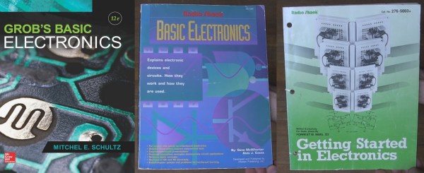
Grob’s Basic Electronics
Grob’s Basic Electronics by Mitchel E Schultz and Bernard Grob is a textbook, one that is easy to read yet very thorough. I bought mine from a used books store. The 1st Edition was published in 1959 and it’s currently on the 12th edition, published in 2015. Clearly this one has staying power.
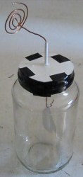
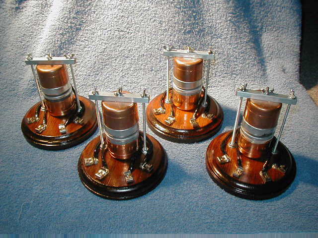
I refer back to it frequently, most often to the chapters on resonance, induction and capacitance when working on LC circuits, like the ones in my crystal radios. There are also things in here that I couldn’t find anywhere else, including thoroughly exhaustive online searches. One such example is the correct definitions and formulas for the various magnetic units: ampere turns, field intensity, flux density…
I’d recommend it to a high school student or any adult who’s serious about knowing electronics well. I’d also recommend it to anyone who wants to reduce frustration when designing or debugging circuits.


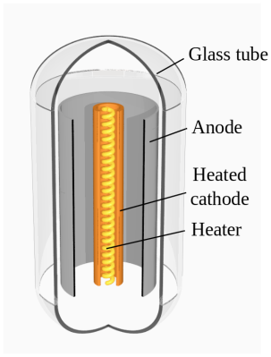
You can find the table of contents here but briefly it has all the necessary introductory material on Ohm’s and Kirchhoff’s laws, parallel and series circuits, and so on but to give you an idea of how deep it goes it also has chapters on network theorems and complex numbers for AC circuits. Interestingly my 1977 4th edition has a chapter on vacuum tubes that’s gone in the current version and in its place is a plethora of new ones devoted to diodes, BJTs, FETs, thyristors and op-amps.
You can also do the practice problems and self-examination, just to make sure you understood it correctly. (I sometimes do them!) But also, being a textbook, the newest edition is expensive. However, a search for older but still recent editions on Amazon turns up some affordable used copies. Most of basic electronics hasn’t changed and my ancient edition is one of my more frequent go-to books. But it’s not the only gem I’ve found. Below are a few more.


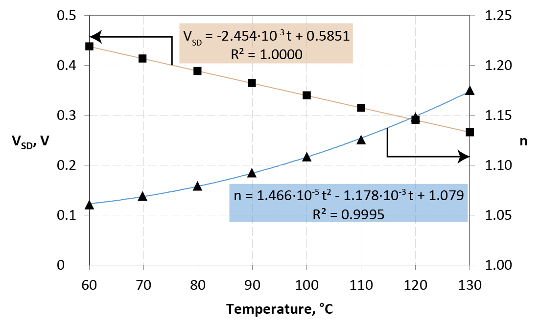
 where
where