Clock Mixes Analog, Digital, Retrograde Displays

Unique clocks are a mainstay around here, and while plenty are “human readable” without any instruction, there are a few that take a bit of practice before someone can glean the current time from them. Word clocks are perhaps on the easier side of non-traditional displays but at the other end are binary clocks or even things like QR code clocks. To get the best of both worlds, though, multiple clock faces can be combined into one large display like this clock build from [imitche3].

The clock is actually three clocks in one. The first was inspired by a binary clock originally found in a kit, which has separate binary “digits” for hour, minute, and second and retains the MAX 7219 LED controller driving the display. A standard analog clock rests at the top, and a third clock called a retrograde clock sits at the bottom with three voltmeters that read out the time in steps. Everything is controlled by an Arduino Nano with the reliable DS3231 keeping track of time. The case can be laser-cut or 3D printed and [imitche3] has provided schematics for both options.

As far as clocks builds go, we always appreciate something which can be used to tell the time without needing any legends, codes, or specialized knowledge. Of course, if you want to take a more complex or difficult clock face some of the ones we’re partial to are this QR code clock which needs a piece of hardware to tell the time that probably already has its own clock on it.

Pixel Graphics From An HD44780, By Cutting Wires

[Felipe Tavares] wasn’t satisfied with the boring default fonts on an HD44780-based display. And while you can play some clever tricks with user-defined characters, if you want to treat the display as an array of pixels, you’ve got to get out your scalpel and cut up a data line.

The hack builds on work from [MisterHW] who documented the bits going from the common display driver to the display, and suggested that by cutting the data line and sending your own bits, you could send arbitrary graphics. The trick was to make sure that they’re in sync with the display, though, which means reading the frame sync line in user code.

This done, it looks like [Felipe] has it working! If you can read Rust for the ESP32, he has even provided us with a working demo of the code that makes it work.

We can’t help but wonder if it’s not possible to go even lower-level and omit the HD44780 entirely. Has anyone tried driving one of these little LCD displays directly from a microcontroller, essentially implementing the HD44780 yourself?

Any way you slice it, this is a cool hack, and it opens up the doors to DOOM, or as [MisterHW] suggests, Bad Apple on these little displays . If you do it, we want to see it.

If your needs aren’t so exotic, the classic HD44780 display is a piece of cake to get working, and an invaluable tool in anyone’s toolbox.

Keep Tabs On PC Use With Custom Analog Voltmeter

With the demands of modern computing, from video editing, streaming, and gaming, many of us will turn to a monitoring system of some point to keep tabs on CPU usage, temperatures, memory, and other physical states of our machines. Most are going to simply display on the screen but this data can be sent to external CPU monitors as well. This retro-styled monitor built on analog voltmeters does a great job of this and adds some flair to a modern workstation as well.

The build, known as bbMonitor, is based on the ESP32 platform which controls an array of voltmeters via PWM. The voltmeters have been modified with a percentage display to show things like CPU use percentage. Software running on the computers sends this data in real time to the ESP32 so the computer’s behavior can be viewed at a glance. Each voltmeter is also augmented with RGB LEDs that change color from green to red as use increases as well. The project’s creator, [Corebb], also notes that the gauges will bounce around if the computer is under heavy load but act more linearly when under constant load, also helping to keep an eye on computer status.

While the build does seem to rely on a Windows machine to run the software for export to the monitor, all of the code is open-sourced and available on the project’s GitHub page and could potentially be adapted for other operating systems. And, as far as the voltmeters themselves go, there have been similar projects in the past that use stepper motors as a CPU usage monitor instead.

Continue reading “Keep Tabs On PC Use With Custom Analog Voltmeter”

ESP32 Weather Station Looks Great With Color E-Paper Display

[educ8s.tv] has built weather stations before, but his latest is his best yet. It’s all thanks to its low-power design, enabled by its e-paper display.

The build is based around an ESP32 microcontroller, combined with a BMP180 sensor for measuring barometric pressure, and a DHT22 sensor for measuring temperature and humidity. By taking these values and feeding them into the Zambretti algorithm, it’s possible to generate a rudimentary weather forecast.

The weather station looks particularly impressive thanks to its six-color e-paper display. It’s brightly colored and easy to read, and displays graphs of temperature, pressure, and humidity over time. Plus, by virtue of the fact that it only draws power when updating, it allows the project to last a long time running solely on battery power.

As far as DIY weather stations go, this is an attractive and clean design that offers plenty of useful data to the user. We’ve seen some other neat builds in this vein before, too.

Continue reading “ESP32 Weather Station Looks Great With Color E-Paper Display”

Custom Multi-Segment E-Ink Displays From Design To Driving

With multi-segment displays, what you see available online is pretty much what you get. LEDs, LCDs, VFDs; if you want to keep your BOM at a reasonable price, you’ve pretty much got to settle for whatever some designer thinks looks good. And if the manufacturer’s aesthetic doesn’t match yours, it’s tough luck for you.

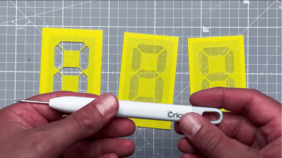
Maybe not though. [upir] has a thing for custom displays, leading him to explore custom-made e-ink displays. The displays are made by a company called Ynvisible, and while they’re not exactly giving away the unique-looking flexible displays, they seem pretty reasonably priced. Since the displays are made with a screen printing process, most of the video below concerns getting [upir]’s preferred design into files suitable for printing. He uses Adobe Illustrator for that job, turning multi-segment design ideas by YouTuber [Posy] into chunky displays. There are some design restrictions, of course, chief of which is spacing between segments. [upir] shows off some Illustrator-fu that helps automate that process, as well as a host of general vector graphics design tips and tricks.

After sending off the design files to Ynvisible and getting the flexible displays back, [upir] walks us through the details of driving them. It’s not as simple as you’d think, at least in the Arduino world; the segments need +1.5 volts with reference to the common connection to turn on, and -1.5 volts to turn off. His clever solution is to use an Arduino Uno R4 and take advantage of the onboard DAC. To turn on a segment, he connects a segment to a GPIO pin set high while sending 3.5 volts out of the DAC output into the display’s common connection. The difference between the two pins is 1.5 volts, turning the segment on. To turn it off, he drops the DAC output to 1.5 volts and drives the common GPIO pin low. Pretty clever, and no extra circuitry is required.

This isn’t the first time we’ve seen [upir] trying to jazz things up in the display department. He’s played with masking LED matrix displays with SMD stencils before, and figured out how to send custom fonts to 16×2 displays too.

Continue reading “Custom Multi-Segment E-Ink Displays From Design To Driving”

Giant Demonstrator Explains How DLP Projectors Work

Texas Instruments developed digital mirror devices, and the subsequent digital light processing (DLP) projector, starting in the late 1980s. The technology is a wondrous and fanciful application of micro-scale electronics and optics. Most of us that have tangled with these devices have had to learn their mode of operation from diagrams and our own imagination. But what if you just built one at a large enough scale that you could see how it worked? Well, [jbumstead] did just that!

A real Digital Micromirror Device (DMD) consists of hundreds of thousands of mirrors, which would be impractical to recreate. This build settles for a simpler 5×5 array made using half-inch square mirrors. It uses solenoids to move each individual mirror between a flat and angled position to create the display. The solenoids are all under the command of an Arduino Mega which controls the overall state of the display and shows various patterns.

It’s not perfect, with the mirrors not quite matching in angles at all times, but it demonstrates the concept perfectly well. When you see it in action with light bouncing off it, you can easily understand how this could be used to make a display of many thousands of pixels in a projector arrangement. We’ve featured some other DLP hacks before, too, so dive in if you’re interested.

Continue reading “Giant Demonstrator Explains How DLP Projectors Work”

Wio Terminal Makes Passable Oscilloscope

There was a time when getting a good oscilloscope not only involved a large outlay of capital, but also required substantial real estate on a workbench. The situation has improved considerably for the hobbyist, but a “real” scope can still cost more than what a beginner is looking to spend. Luckily, plenty of modern microcontrollers are capable of acting as a basic oscilloscope in a pinch, provided there’s a display available to interface with it. Combined with the right software, the Wio Terminal looks like a promising option.

The Wio Terminal is a platform gaining some popularity due to its fairly capable SAMD51 microcontroller and also its integration with a display and a number of input buttons. On the hardware side, [mircemk] mounted the Terminal in a convenient vertical orientation and broke out a pair of connectors for the inputs.

But it’s the software that really makes this project work. [Play With Microcontroller] originally developed the firmware for the PIC24 back in 2017, but ported the code over to the Wio Terminal a couple years back. Noting that the microcontroller is not particularly fast, the project doesn’t exactly match the specifications or capabilities of a commercial unit. But still, it does an impressive job of recreating the experience of using a modern digital scope

The Wio Terminal is a device we’ve seen around here for a few unique projects, among them a device for preventing repetitive strain injuries while using a computer mouse and another that is a guide for game development in MicroPython. And if you’re just itching to port oscilloscope software to accessible but under-powered microcontrollers, be sure to check out [mircemk]’s other oscilloscope projects like this one built around the STM32 microcontroller.

Continue reading “Wio Terminal Makes Passable Oscilloscope”