Flexible PCB Robot Flops Around To Get Around

In his continuing quest to reduce the parts count of a robot as far as possible, [Carl Bugeja] has hit upon an unusual design: robots built of almost nothing but PCBs.

Admittedly, calling these floppy four-legged critters robots is still a bit of a stretch at this point. The video below shows that while they certainly move under their own power, there’s not a lot of control to the movement – yet. [Carl]’s design uses an incredibly fragile looking upper arm assembly made from FR4. Each arm holds a small neodymium magnet suspended over the center of a flexible PCB coil, quite like those we’ve seen him use before as actuators and speakers. The coils are controlled by a microcontroller living where the four legs intersect. After a few uninspiring tethered tests revealed some problems with the overly compliant FR4 magnet supports, [Carl] made a few changes and upped the frequency of the leg movements. This led to actual motion and eventually to untethered operation, with the bot buzzing around merrily.

There are still issues with the lack of stiffness of the magnet arms, but we’re optimistic that [Carl] can overcome them. We like this idea a lot, and can see all sort of neat applications for flapping and flopping locomotion.

Continue reading “Flexible PCB Robot Flops Around To Get Around”

Three-Conductor Pivot For E-Textiles Is Better Than Wires

Pivots for e-textiles can seem like a trivial problem. After all, wires and fabrics bend and flex just fine. However, things that are worn on a body can have trickier needs. Snap connectors are the usual way to get both an electrical connection and a pivot point, but they provide only a single conductor. When [KOBAKANT] had a need for a pivoting connection with three electrical conductors, they came up with a design that did exactly that by using a flexible circuit board integrated to a single button snap.

This interesting design is part of a solution to a specific requirement, which is to accurately measure hand movements. The photo shows two strips connected together, which pivot as one. The metal disk near the center is a magnet, and underneath it is a Hall effect sensor. When the wrist bends, the magnet is moved nearer or further from the sensor and the unit flexes and pivots smoothly in response. The brief videos embedded below make it clear how the whole thing works.

Continue reading “Three-Conductor Pivot For E-Textiles Is Better Than Wires”

Crawling PCB ‘Bot Is Flexible Where It Counts

20 years ago, PCB production was expensive and required a multitude of phone calls and emails to a fab with significant minimum order restrictions. Now, it’s cheap and accessible online, which in addition to curtailing the home etching market has created significant new possibilities for home projects. Now that flexible PCBs are also readily available, it’s possible to experiment with some cool concepts – and that’s precisely what [Carl] has been doing.

The aim is to build a walking robot that uses actuators made from flexible PCBs. The flexible PCB is printed with a coil, capable of generating a small magnetic field. This then interacts with a strong permanent magnet, causing the flexible PCB to move when energised.

Initial attempts with four actuators mounted to a 3D printed frame were unsuccessful, but [Carl] has persevered. With a focus on weight saving, the MK II prototype has shown some promise, gently twitching its way across a desk in testing. Future steps will involve building an untethered version. This will replace the 3D printed chassis with a standard fibreglass PCB acting as both control board and the main chassis to minimise weight, similar to PCB quadcopter designs we’ve seen in the past.

We can’t wait to see the next revision, and if you’ve been working on your own walking robots, make sure you let us know.

You Can Add Wireless Charging To IPhone… Kinda

We could watch cellphone teardown videos all day long. There’s something pleasing about seeing how everything is packed into such a small enclosure. From the connectors, to that insidious glue, to the minuscule screws, [Scotty Allen] has a real knack for giving us a great look at the teardown process. Take a look at his latest video which attempts to add wireless charging to an iPhone. I think there’s a lot to be said for superb lighting and a formidable camera, but part of this is framing the shots just right.

Now of course we’ve taken apart our fair share of phones and there’s always that queasy “I think I’m going to break something” feeling while doing it. It’s reassuring that [Scotty] isn’t able to do things perfectly either (although he has the benefit of walking the markets for quick replacement parts). This video is a pretty honest recounting of many things going wrong.

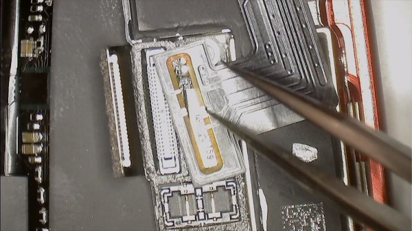
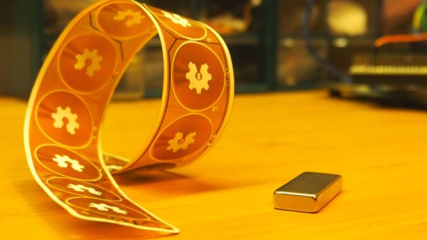
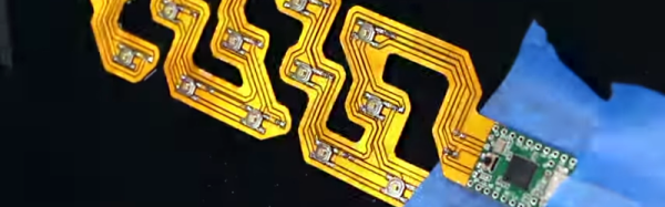
The iPhone 6 and 7 are not meant to have wireless charging, but [Scotty’s] working with a friend named [Yeke] who created an aftermarket kit for this. The flexible PCB needs to be folded just right, and adhesive foam added (along with a magical incantation) to make it work. That’s because the add-on is a no-solder job. Above you can see it cleverly encircles one of the mating connectors and relies on mechanical pressure to make contact with the legs of that connector. Neat!

In the second half of the video [Scotty] meets up with [Yeke] to discuss the design itself. We find it interesting that [Yeke] considers his work a DIY item. Perhaps it’s merely lost in translation, but perhaps [Yeke’s] proximity to multiple flexible PCB manufacturers makes him feel that this is more like playing around for fun than product design. Any way you look at it, the ability to design something that will fit inside that crazy-tight iPhone case is both impressive and mesmerizing. Having seen some of the inductive charging hacks over the years, this is by far the cleanest way to go about it.

We caught up with [Scotty] during last year’s Supercon. We may not be able to drop everything and move to Shenzhen, but hearing about the experience is just enough to keep us wanting to!

Continue reading “You Can Add Wireless Charging To IPhone… Kinda”

Flexible PCB Becomes The Actuator

An electromagnetic coil gun takes a line of electromagnets working together to form a moving electromagnetic field. These fields accelerate a project and boom, you have electricity moving matter, often at an impressive rate of speed.

[Carl Bugeja] has taken the idea and in a sense turned it upon its head with his flexible PCB actuator. Now the line of electromagnets are the moving part and the magnetic object the stationary one. There is still a line of flat PCB inductors in the classic coil gun configuration, but as the title suggests on a flexible substrate.

The result is a curiously organic motion reminiscent of some lizards, caterpillars, or snakes. It can move over the magnet in a loop, or flex in the air above it. It’s a novel moving part, and he’s treated us to a video which we’ve placed below the break.

He has plans to put it to use in some form of robot, though while it certainly has promise we’d be interested to know both what force it can produce and whether flexible PCB is robust enough for repeated operation. We salute him for taking a simple idea and so effectively proving the concept.

We’ve brought you [Carl]’s work before, most notably with his PCB motor.

Continue reading “Flexible PCB Becomes The Actuator”

Print A Flexible Keypad

[Micah Elizabeth Scott] needed a custom USB keyboard that wrapped around a post. She couldn’t find exactly what she wanted so she designed and printed it using flexible Nijaflex filament. You can see the design process and the result in the video below.

The electronics rely on a Teensy, which can emulate a USB keyboard easily. The keys themselves use the old resistor divider trick to allow one analog input on the Teensy to read multiple buttons. This was handy, but also minimized the wiring on the flexible PCB.

The board itself used Pyralux that was milled instead of etched. Most of the PCB artwork was done in KiCAD, other than the outline which was done in a more conventional CAD program.

Continue reading “Print A Flexible Keypad”

Print Flexible PCBs With A 3D Printer

Let’s get it out of the way right up front: you still need to etch the boards. However, [Mikey77] found that flexible plastic (Ninjaflex) will adhere to a bare copper board if the initial layer height is set just right. By printing on a thin piece of copper or conductive fabric, a resist layer forms. After that, it is just simple etching to create a PCB. [Mikey77] used ferric chloride, but other etchants ought to work, as well.

Sound simple, but as usual, the devil is in the details. [Mikey77] found that for some reason white Ninjaflex stuck best. The PCB has to be stuck totally flat to the bed, and he uses spray adhesive to do that. Just printing with flexible filament can be a challenge. You need a totally constrained filament path, for one thing.

Continue reading “Print Flexible PCBs With A 3D Printer”