Rapid Prototyping PCBs With The Circuit Graver

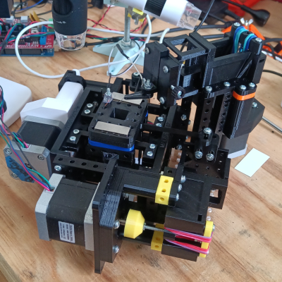
Walking around the alley at Hackaday Supercon 2024, we noticed an interesting project was getting quite a bit of attention, so we got nearer for a close-up. The ‘Circuit Graver’ by [Zach Fredin] is an unconventional PCB milling machine, utilizing many 3D printed parts, the familiar bed-slinger style Cartesian bot layout and a unique cutting head. The cutting tool, which started life as a tungsten carbide lathe tool, is held on a rotary (‘R’) axis but can also move vertically via a flexure-loaded carriage driven by a 13 kg servo motor.

The stocky flexure took a lot of iteration, as the build logs will show. Despite a wild goose chase attempting to measure the cutting force, a complete machine solution was found by simply making everything stiff enough to prevent the tool from chattering across the surface of the FR4 blank. Controlling and maintaining the rake angle was a critical parameter here. [Zach] actually took an additional step, which we likely wouldn’t have thought of, to have some copper blanks pre-fabricated to the required size and finished with an ENIG coating. It’s definitely a smart move!


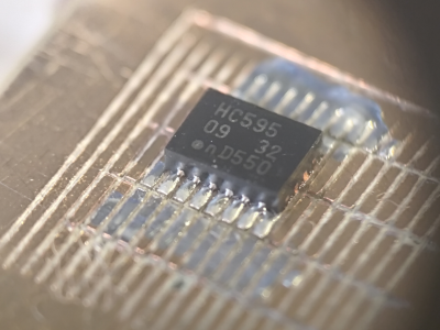
To allow the production of PCB-class feature sizes compatible with a traditional PCB router, the cutting tool was sharpened to a much smaller point than would be used in a lathe using a stone. This reduced the point size sufficiently to allow feature sizes down to 4 mils, or at least that’s what initial characterization implied was viable.  As you can see from the build logs, [Zach] has achieved a repeatable enough process to allow building a simple circuit using an SMT 74HC595 and some 0402 LEDs to create an SAO for this year’s Supercon badge. Neat stuff!

We see a fair few PCB mills, some 3D printed, and some not. Here’s a nice one that fits in that former category. Milling PCBs is quite a good solution for the rapid prototyping of electronics. Here’s a guide about that.

Continue reading “Rapid Prototyping PCBs With The Circuit Graver”

Flexures Make Robotic Fingers Simpler To Print

Designing an anthropomorphic robotic hand seems to make a lot of sense — right up until the point that you realize just how complex the human hand is. What works well in bone and sinew often doesn’t translate well to servos and sensors, and even building a single mechanical finger can require dozens of parts.

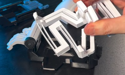
Or, if you’re as clever about things as [Adrian Perez] is, only one part. His print-in-place robotic finger, adorably dubbed “Fingie,” is a huge step toward simplifying anthropomorphic manipulators. Fingie is printed in PLA and uses flexures for the three main joints of the finger, each of which consists of two separate and opposed coil springs. The flexures allow the phalanges to bend relative to each other in response to the motion of three separate tendons that extend through a channel on the palmar aspect of the finger, very much like the real thing.

The flexures eliminate the need for bearings at each joint and greatly decrease the complexity of the finger, but the model isn’t perfect. As [Adrian] points out, the off-center attachment for the tendons makes the finger tend to curl when the joints are in flexion, which isn’t how real fingers work. That should be a pretty easy fix, though. And while we appreciate the “one and done” nature of this print, we’d almost like to see the strap-like print-in-place tendons replaced with pieces of PLA filament added as a post-processing step, to make the finger more compact and perhaps easier to control.

Despite the shortcomings, and keeping in mind that this is clearly a proof of concept, we really like where [Adrian] is going with this, and we’re looking forward to seeing a hand with five Fingies, or four Fingies and a Thumbie. It stands to be vastly simpler than something like [Will Cogley]’s biomimetic hand, which while an absolute masterpiece of design, is pretty daunting for most of us to reproduce.

Continue reading “Flexures Make Robotic Fingers Simpler To Print”

Flexures Keep This Printed Displacement Sensor In Line

When the job at hand is measuring something with micron-range precision, thoughts generally turn to a tool with a Mitutoyo or Starrett nameplate. But with a clever design and a little electronics know-how, it turns out you can 3D print a displacement sensor for measuring in the micron range for only about $10.

While the tool that [BubsBuilds] came up with isn’t as compact as a dial indicator and probably won’t win any industrial design awards, that doesn’t detract from its usefulness. And unlike a dial indicator — at least the analog type — this sensor outputs an easily digitized signal. That comes courtesy of a simple opto-interrupter sensor, which measures the position of a fine blade within its field of view. The blade is attached to a flexure that constrains its movement to a single plane; the other end of the flexure has a steel ball acting as a stylus. In use, any displacement of the stylus results in more or less light being received by the phototransistor in the opto-interrupter; the greater the deflection, the less light and the lower the current through the transistor. In addition to the sensor itself, [Bub] printed a calibration jig that allows precision gauge blocks or simple feeler gauges to be inserted in front of the stylus. The voltage across the emitter resistor for these known displacements is then used to create a calibration curve.

[Bub] says he’s getting 5-micron repeatability with careful calibration and multiple measurements of each gauge block, which seems pretty impressive to us. If you don’t need the digital output, this compliant mechanism dial indicator might be helpful too. Continue reading “Flexures Keep This Printed Displacement Sensor In Line”

Squid-Con Brings Joy To All

While we’re always happy to see accessibility aids come into fruition, most of them focus on daily tasks, not that there’s anything wrong with that. But what about having some fun? That’s the idea behind [Akaki Kuumeri]’s accessibly-awesome Joy-Con controller, the Squid-Con, which provides access to every button with just one hand. It even has tripod and AMPS mounts.

The joysticks themselves are controlled with the thumb and pinky, although some of [Akaki]’s beta testers changed it up a bit. That’s okay, because it’s designed to be comfortable in a variety of positions for either hand. As for the ABXY buttons, those are actuated using 3D-printed arms that connect to a central piece which [Akaki] calls the turbine.

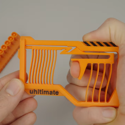
But perhaps the coolest part of this project is the flexures that actuate the shoulder buttons (L, R, zL, and zR) on the controllers. It’s a series of four arms that are actuated by bringing the fingers back toward the palm. If all of this sounds confusing, just check out the video after the break.

We love flexures around here, and we’ve seen them in everything from cat feeding calendars to 6-DOF positioners to completely new kinds of joysticks.

Continue reading “Squid-Con Brings Joy To All”

Physical Neural Network Can Be Trained Like A Digital One

Here’s an unusual concept: a computer-guided mechanical neural network (video, embedded below.) Why would one want a mechanical neural network? It’s essentially a tool to explore what it would take to make physical materials work in nonstandard ways. The main part is a lattice of interlinked mechanical components. When one applies a certain force in a certain direction on one end, it causes the lattice to deform in a non-intuitive way on the other end.

To make this happen, individual mechanical elements  in the lattice need to have their compliance carefully tuned under the guidance of a computer system. The mechanisms shown can be adjusted on demand while force is applied and cameras monitor the results.

This feedback loop allows researchers to use the same techniques for training neural networks that are used in machine learning applications. Ultimately, a lattice can be configured in such a way that when side A is pressed like this, side B moves like that.

We’ve seen compliant structures that move in unexpected ways before, and they are always fascinating. One example is this 3D-printed door latch that translates a twisting motion into a linear one. Research into physical neural networks seems like it might open the door to more complex systems, or provide insights into metamaterial design.

You can watch the video below just under the page break, or if you prefer, skip the intro and jump straight into How It Works at [2:32].

Continue reading “Physical Neural Network Can Be Trained Like A Digital One”

This Block Of Rubber Can Count To Ten

Complex behaviors can arise from simple mechanics, and that’s demonstrated by a block of rubber that acts as a counter.

The block contains beams, and by controlling how the block is compressed, the vertical beams shift in a stable and consistent way, acting as a mechanical counter. It’s a straightforward implementation of the work of two physicists from the Netherlands: [Martin van Hecke] and [Lennard Kwakernaak].

This device brings flexures to mind, which are also examples of obtaining complex and useful behavior from seemingly simple objects. We’ve seen flexures used as latches and counters, and we’ve seen 3D printed flexures as a kind of linear actuator.

You can check out the research paper for more details on the rubber beam counter. [Kwakernaak] aims to create a much more complex structure with elements that interact across a plane instead of in a single direction. Such a device would, in effect, be a simple computer.

Watch the beam counter in action in the short video embedded below. See how the elements of the green rubber block move while constrained by an outer frame that helps control the force that is applied. The thin beams flip from left to right, one at a time with each press.

Continue reading “This Block Of Rubber Can Count To Ten”

A man sits in front of a wooden table. There is a black box with a number of knobs hand-labeled on blue painter's tape. A white breadboard with a number of wires protruding from it is visible on the box's left side. An oscilliscope is behind the black box and has a yellow waveform displaying on its screen.

A More Expressive Synth Via Flexure

Synthesizers can make some great music, but sometimes they feel a bit robotic in comparison to their analog counterparts. [Sound Werkshop] built a “minimum viable” expressive synth to overcome this challenge. (YouTube)

Dubbed “The Wiggler,” [Sound Werkshop]’s expressive synth centers on the idea of using a flexure as a means to control vibrato and volume. Side-to-side and vertical movement of the flexure is detected with a pair of linear hall effect sensors that feed into the Daisy Seed microcontroller to modify the patch.

The build itself is a large 3D printed base with room for the flexure and a couple of breadboards for prototyping the circuits. The keys are capacitive touch pads, and everything is currently held in place with hot glue. [Sound Werkshop] goes into detail in the video (below the break) on what the various knobs and switches do with an emphasis on how it was designed for ease of use.

If you want to learn more about flexures, be sure to checkout this Open Source Flexure Construction Kit.

Continue reading “A More Expressive Synth Via Flexure”