A Wearable Space Station Notifier

If you don’t live in northern Europe, Alaska, or the extreme southern part of South America, there’s a 400-ton, $150 Billion space station flying over your head several times a day. It’s the International Space Station, and it’s the most complex and expensive construction project of all time. Look up at the right time, and you can see a point of light rising in the sky, brighter than any star, darting across to the opposite horizon.

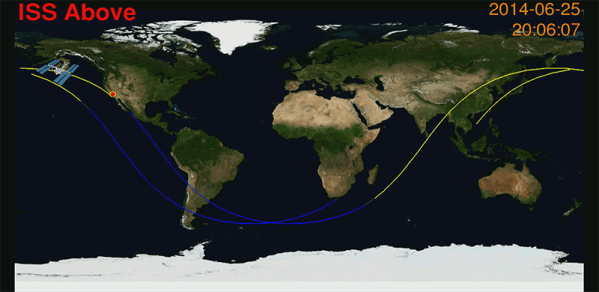
ISS-Above is a simple tool that will tell you when you’ll be able to see the ISS passing overhead next, and the creator of the project, [Liam Kennedy] has a new crowdfunding project to turn this space station notifier into a wearable. It’s called the Pulsar, and with the help of an RFduino and a real time clock, it will alert you to an upcoming station pass with a bit of wearable electronics.

ISS
Viewing the ISS at the most recent Hackaday Pasadena Meetup.

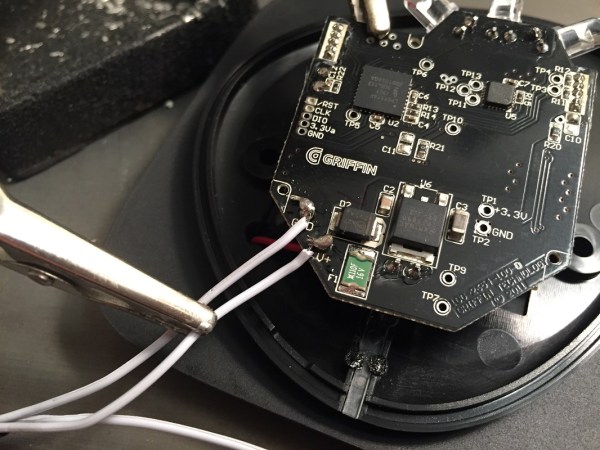
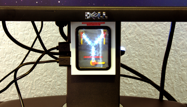
The ISS-Above is a great device to keep tabs on the six astronauts currently orbiting our globe, but if you want to see the space station rise over the horizon… well, lugging a Raspi and an HDMI monitor outside isn’t the best solution. The Pulsar is a tiny wearable board with a ring of LEDs programmed with 50 future passes of the space station. When the station is overhead, the LEDs light up, and a bright object appears over the western horizon.

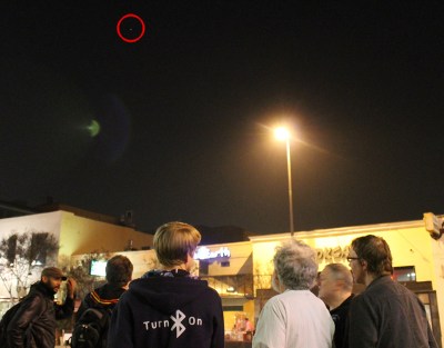
[Liam] brought his Pulsar to the most recent Hackaday Pasadena meetup, and as his wearable LEDs lit up, the ISS appeared right on cue. The evening was only tainted by a crazy lady who decided to argue the existence of the International Space Station.

Video below.

Continue reading “A Wearable Space Station Notifier”

Balancing A Ball With A Solar Cell

Go to any control systems class, and you’ll see a final project that demonstrates loops, integration, and everything else that can be learned in a semester or two of control theory. This project is not from one of those classes. It is, however, very cool: it balances a 40mm steel ball on the rim of a lasercut wood wheel using nothing more than a solar cell as a sensor.

[Manuel] was inspired to build this ball-balancing device after seeing a similar project at CCC about six years ago. He doesn’t remember who made it, and eschewed the PC/Matlab architecture of the original, but this build retains one interesting feature of its muse. The input to the control system is just a high intensity light bulb and a solar cell. The 40mm steel ball blocks the light reaching the solar cell most of the time. Slight variations in voltage go through the control system to keep this ball balanced on top of the wheel.

The only hardware for this build is a motor, a motor driver, and an ATMega644P. The first revision of the hardware was just a few breakout boards stuffed into a rat’s nest of wiring in the base of the build, but this has been fixed in version two with a new PCB. Video below.

Continue reading “Balancing A Ball With A Solar Cell”

A Class D Amp Made From Scrap

[Boolean90] needed an amplifier for a subwoofer, and had a lot of parts sitting around in a scrap bin. His project, a Class D sub amp made out of scrap, is a great example of what you can build with the right know-how and a very large pile of junk.

With digital logic and PWM chips, a Class D amp is one of the simpler ways to get a lot of amplification easily in an efficient package. It’s really not that complicated; an audio signal is turned into a PWM’d square wave, this is sent out to a Mosfet bridge, and finally out to the speaker.

Most Class D amps have a switching frequency of hundreds of kilohertz to the Megahertz range, but since this is an amplifier for a subwoofer that has a cutoff frequency of about 1kHz, the switching frequency doesn’t need to be quite as fast. [Boolean] is using a 50kHz carrier frequency; it’s more than high enough to recreate low frequencies.

With the completed project, [Boolean] has an extremely loud amplifier that has around 75-150W of output power. The subwoofer is only rated for 200W, but with the volume [Boolean] is getting, this isn’t an amp he’ll be rebuilding anytime soon.

Show Me The Data: Hackaday.io Year #01

Today marks exactly one year since we announced to the world the first product from our software lab – Hackaday.io. In what has been an incredibly exciting year for all of us, we evolved from a simple idea and a prototype to a truly massive community that’s making its mark on the world. Day after day, carefully listening to the invaluable feedback from our users, we have improved and moved forward, one line of code at the time.

We still have a long way to go, but we’ll pause for a second now and reflect on how far we’ve come. Then get right back to fixing bugs and developing new features.

It all started with a simple idea – building a better project hosting website. Though there are project and content websites galore out there, with new ones popping up every day, it all still felt too bland. We thought we could do better. After all, the medium is the message. The place where something lives sooner or later becomes a key part of its identity. So in order to prevent a dystopian future in which we’re all hosting our projects using the (fictional) Microsoft Maker Suite 2020 and simply don’t care, we started to work on providing an alternative.

We quickly realized that we had a much bigger mission on our hands. Sure, a better project hosting website would be nice, but what we felt we really needed was something [Brian Benchoff] has been talking about for quite some time – a “virtual hackerspace.” Not just a place where you can post your builds once you’re done (and hope someone sees it), but a living, breathing community: a place where you can start with an idea and get feedback as it develops, find collaborators, iterate, and ultimately end up building something way more amazing than you would have accomplished on your own.

This has been the aim of Hackaday for many years, but most of the collaboration was constrained to the limited space of post comment threads and biased by the editorial choice of articles and topics. With the introduction of Hackaday.io, we open up a space for anyone to unleash their creativity and expertise, and together, change the way people build things.

The Data

Unfortunately, making bold claims about how we’re out there changing the world is pretty much a commodity these days. As most Web startups can testify, it doesn’t take more than a simple landing page with nice photography and some uplifting message for any arbitrary claims to appear credible.

So instead of trying to convince you with words about how awesome the last year had been, we’ll just stick with the data.

Continue reading “Show Me The Data: Hackaday.io Year #01”

Flux Capacitor

Great Scott! A Flux Capacitor Notification Light

If you are into your social media, then you probably like to stay updated with your notifications. [Gamaral] feels this way but he wasn’t happy with the standard way of checking the website or waiting for his phone to alert him. He wanted something a little more flashy. Something like a flux capacitor notification light. This device won’t send his messages back in time, but it does look cool.

He started with an off-the-shelf flux capacitor USB charger. Normally this device just looks cool when charging your USB devices. [Gamaral] wanted to give himself more control of it. He started by opening up the case and replacing a single surface mount resistor. The replacement component is actually a 3.3V regulator that happens to be a similar form factor as the original resistor. This regulator can now provide steady power to the device itself, as well as a ESP8266 module.

The ESP8266 module has built-in WiFi capabilities for a low price. The board itself is also quite small, making it suitable for this project. [Gamaral] used just two GPIO pins. The first one toggles the flux circuit on and off, and the second keeps track of the current state of the circuit. To actually trigger the change, [gamaral] just connects to the module via TCP and issues a “TIME CIRCUIT ON/OFF” command. The simplicity makes the unit more versatile because an application running on a PC can actually track various social media and flash the unit accordingly.

Mapping WiFi Signals In 3 Dimensions

[Charles] is on a quest to complete ever more jaw-dropping hacks with the popular low-cost ESP8266 WiFi modules. This week’s project is plotting WiFi received signal strength in 3D space. While the ESP8266 is capable of providing a Received Signal Strength Indication (RSSI), [Charles] didn’t directly use it. He wrote a simple C program on his laptop to ping the ESP8266 at around 500Hz. The laptop would then translate the RSSI from the ping replies to a color value, which it would then send to the ESP8266. Since the ESP8266 was running [Charles’] custom firmware (as seen in his WiFi cup project), it could directly display the color on a WS2812 RGB LED.

The colors seemed random at first, but [Charles] noticed that there was a pattern. He just needed a way to visualize the LED over time. A single frame long exposure would work, but so would video. [Charles] went the video route, creating SuperLongExposure, an FFMPEG-based tool which extracts every video frame and composites them into a single frame. What he saw was pretty cool – there were definite stripes of good and bad signal.

wifiPOVThumb
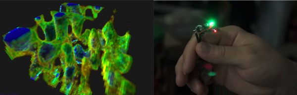
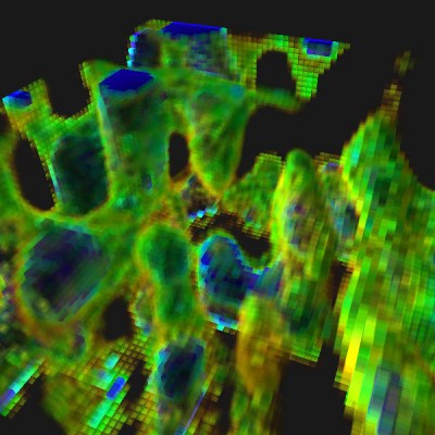
Armed with this information, [Charles] went for broke and mounted his ESP8266 on a large gantry style mill. He took several long exposure videos of a 360x360x180mm area. The videos were extracted into layers. The whole data set could then be visualized with Voxeltastic, [Charles’] own HTML5/WEBGL based render engine. The results were nothing short of amazing. The signal strength increases and decreases in nodes and anti-nodes which correspond to the 12.4 cm wavelength of a WiFi signal. The final render looks incredibly organic, which isn’t completely surprising. We’ve seen the same kind of image from commercial antenna simulation characterization systems.

Once again [Charles] has blown us away, we can’t wait to see what he does next!

Continue reading “Mapping WiFi Signals In 3 Dimensions”

remote circuit board

Ultimate Remote Is Ultimate

[Joedefa] had a Griffin Beacon Universal Remote that was collecting dust, and decided that it needed to stop collecting dust. He had a growing number of wireless devices in his house and found himself in need of a remote to control them all. The Griffin Beacon fit the bill, but most of his lights and outlets were RF controlled. So he did what hackers do best… broke out the screw driver and soldering iron and rewired it!

[Joedefa] is using an Attiny85 as the brains between an infrared LED and a RF transmit module (if anyone can identify the source of this module, please let everyone know in the comments).  A pair of red and green LEDs lets him know if the remote has received commands successfully.

It’s always nice to see a discontinued product made useful once more with a little ingenuity and an Arduino some hacking skill. Hat’s off to [Joedefa] for a righteous hack!