LayerLapse Simplifies 3D Printer Time-lapse Shots

We know you’ve seen them: the time-lapses that show a 3D print coming together layer-by-layer without the extruder taking up half the frame. It takes a little extra work compared to just pointing a camera at the build plate, but it’s worth it to see your prints materialize like magic.

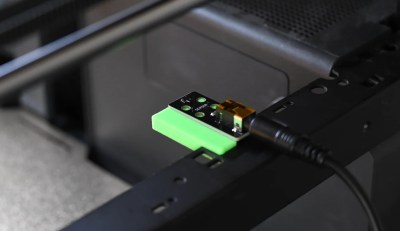
Usually these are done with a plugin for OctoPrint, but with all due respect to that phenomenal project, it’s a lot to get set up if you just want to take some pretty pictures. Which is why [Whopper Printing] put together the LayerLapse. This small PCB is designed to trigger your DSLR or mirrorless camera once its remotely-mounted hall effect sensor detects the presence of a magnet.

The remote hall effect sensor.

The idea is that you just need to stick a small magnet to your extruder, add a bit of extra G-code that will park it over the sensor at the end of each layer, and you’re good to go. There’s even a spare GPIO pin broken out should you want to trigger something else on each layer of your print. Admittedly we can’t think of anything else right now that would make sense, other than some other type of camera, but we’re sure some creative folks out there could put this feature to use.

Currently, [Whopper Printing] is selling the LayerLapse as a finished product, though it does sound like a kit version is in the works. There’s also instructions for building a DIY version of the hardware using your microcontroller of choice. Whether you buy or build the hardware, the firmware is available under the MIT license for your tinkering pleasure.

Being hardware hackers, we appreciate the stand-alone nature of this solution. But if you’re already controlling your printer through OctoPrint, you’re probably better off just setting up one of the available time-lapse plugins.

Trinteract, a small space mouse, operating in Blender.

Trinteract Mini Space Mouse Does It In 3D

We’re not sure how we managed to miss this one, but better late than never, right? This is Trinteract, a 3-DOF input device that’s both open-source and Arduino compatible. There’s even a neat 3D-printed clip to add it to the side of your laptop.

Imagine navigating 2D and 3D environments, or flying around in Minecraft with ease. [Görkem]’s custom PCB features a Hall effect sensor which picks up readings from the magnet embedded in the bottom of the joystick. You can use any magnetic object as input. In the video below the break, [Görkem] shows a 3D-printed sphere with a disc magnet trapped inside as an alternative. The super-neat part is that the thing moves around entirely on flexures. You know how much we love flexures around here.

[Görkem] has written up a fantastic guide for those who must have one of their own. As a bonus, the guide details the background and thought process behind the design, which we love to see.

Don’t like magnets? This space mouse uses an accelerometer and a spring.

Continue reading “Trinteract Mini Space Mouse Does It In 3D”

This WiFi Filament Sensor Is Unnecessary, But Awesome

As desktop 3D printers have inched towards something resembling the mainstream, manufacturers have upped their game across the board. Even the quality of filament that you can get today is far better than what was on the market in the olden days, back when a printer made out of laser-cut birch wasn’t an uncommon sight at the local makerspace. Now, even the cheap rolls are wound fairly well and are of a consistent diameter. For most folks, you just need to pick a well-reviewed brand, buy a roll, and get printing.

But as with everything else, there are exceptions. Some people are producing their own filaments, or want to make sure their extrusion rate is perfectly calibrated. For those that need the capability, the WInFiDEL from [Sasa Karanovic] can detect filament diameter in real-time while keeping the cost and complexity as low as possible. Even better, with both the hardware and software released as open source, it makes an excellent starting point for further development and customization.

Continue reading “This WiFi Filament Sensor Is Unnecessary, But Awesome”

A DIY split-flap clock in red, black, and white.

Split-Flap Clock Uses Magnets Everywhere

While split-flap alarm clocks once adorned heavy wood nightstands in strong numbers, today the displays are most commonly found in train stations and airports. Hey, at least they’re still around, right? Like many of us, [The Wrench] has always wanted to make one for themselves, but they actually got around to doing it.

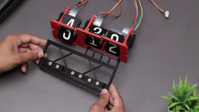
A DIY split-flap clock and its magnetic base.This doesn’t seem like a beginner-friendly project, but [The Wrench] says they were a novice in 3D design and so used Tinkercad to design all the parts. After so many failures, they settled on a design for each unit that uses a spool to attach the flaps, which is turned by a stepper motor.

A small neodymium magnet embedded in the primary gear and a Hall effect sensor determine where the stepper motor is, and in turn, which number is displayed. Everything is handled by an Arduino Nano on a custom PCB.

Aside from the sleek, minimalist look, our favorite part is that [The Wrench] used even more magnets to connect each display segment to the base. You may have noticed that there are only three segments, because the hours are handled by a single display that has flaps for 10, 11, and 12. This makes things simpler and gives the clock an interesting look. Be sure to check out the build video after the break.

Want to build a more complicated clock? Try suspending sand digits in the air with persistence of vision.

Continue reading “Split-Flap Clock Uses Magnets Everywhere”

Simple Magnetic Levitator

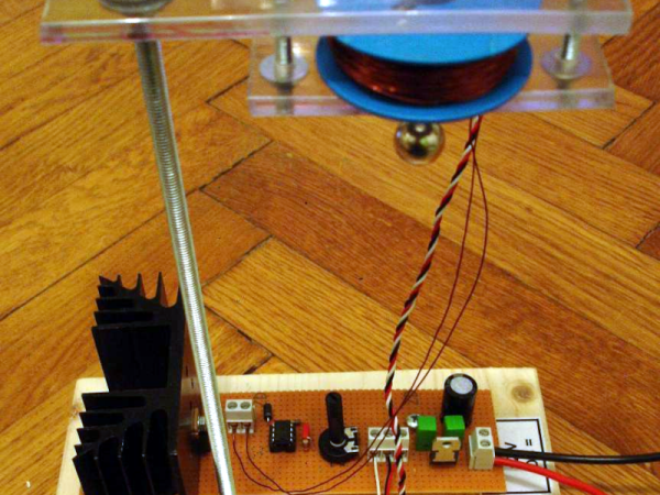
[Stoppi] always has exciting projects and, as you can see in the video below, the latest one is a very simple magnetic levitator design. The design is classic and simple: a 5 V regulator IC, a Hall effect sensor, a 741 op amp, and a MOSFET to turn the electromagnet on and off.

Sure, there are a few passive components and a diode, too, but nothing exotic. The sensor normally presents 2.5 V of output. The voltage rises or drops depending on the polarity of the magnetic field. The stronger the field, the more the voltage changes away from the 2.5 V center.

The op amp acts as a comparator with a potentiometer setting the trip point. As the ball moves up towards the coil, the voltage increases, triggering the comparator, which turns off the FET. With no current through the coil, there’s no more electromagnet, and the ball starts to fall.

Of course, as the ball falls, the voltage from the sensor also drops, and this eventually turns on the electromagnet. The ball eventually reaches a relatively stable position.

This is one of those cases where a simple analog circuit might work better than a digital one. Or make it hard on yourself and use an FPGA.

Continue reading “Simple Magnetic Levitator”

A shot of the underside of a "One Fast Cat" cat wheel with an installed ESP8266 and hall effect sensors attached to the base.

Spy On Your Cat To Make Sure It Gets Its Paws In

[Scott Cutler] has a young cat, [Cygnus], that loves to run on a cat wheel and [Scott] had some some important questions about [Cygnus]’s usage of the cat wheel like, how often it’s used, what direction is preferred and how fast does [Cygnus] go. To answer these questions, [Scott] put some telemetry sensors onto the cat wheel and analyzed the results.

An ESP8266 microcontroller and two 3144E hall effect modules were used to sense eight magnets glued onto the outer housing of a “One Fast Cat” cat wheel. [Scott] installed the ESP8266 and hall effect modules onto the base support for the wheels, using 3D printed brackets to secure them.

For the software side, the ESP8266 attaches an interrupt handler whenever a sensor passes by, recording a window of three previous measurements for valid sample determination and, if accepted, uses the time between samples to infer direction and speed. The ESP8266 connects to a pre-configured local WiFi network and has a telnet interface to extract stored log information, in the form of JSON data.

[Scott] has some nice graphs and other data visualizations on [Cygnus]’s usage, including a preference for running at 3 AM, achieving a maximum speed of 14 mph and an average of 4 seconds per run. The source is available on GitHub and the STL files are available embedded in [Scott]’s write-up. We’ve featured cat exercise trackers before with a giant hamster wheel outfitted with a Raspberry Pi and it’s nice to see some options that allow for a retrofit option in addition to a complete DIY solution.

A man sits in front of a wooden table. There is a black box with a number of knobs hand-labeled on blue painter's tape. A white breadboard with a number of wires protruding from it is visible on the box's left side. An oscilliscope is behind the black box and has a yellow waveform displaying on its screen.

A More Expressive Synth Via Flexure

Synthesizers can make some great music, but sometimes they feel a bit robotic in comparison to their analog counterparts. [Sound Werkshop] built a “minimum viable” expressive synth to overcome this challenge. (YouTube)

Dubbed “The Wiggler,” [Sound Werkshop]’s expressive synth centers on the idea of using a flexure as a means to control vibrato and volume. Side-to-side and vertical movement of the flexure is detected with a pair of linear hall effect sensors that feed into the Daisy Seed microcontroller to modify the patch.

The build itself is a large 3D printed base with room for the flexure and a couple of breadboards for prototyping the circuits. The keys are capacitive touch pads, and everything is currently held in place with hot glue. [Sound Werkshop] goes into detail in the video (below the break) on what the various knobs and switches do with an emphasis on how it was designed for ease of use.

If you want to learn more about flexures, be sure to checkout this Open Source Flexure Construction Kit.

Continue reading “A More Expressive Synth Via Flexure”