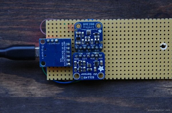
Hooking up I2C sensors is something which is generally associated with microcontrollers and SBCs, yet it’s very easy to use such I2C sensors from basically any system that runs Linux. After all, I2C (that is, SMBus) is one of the interfaces that is highly likely to be used on your PC’s mainboard as well as peripherals. This means that running our own devices like the well-known BME280 temperature, pressure and humidity sensor, or Si1145 light sensor should be a piece of cake.
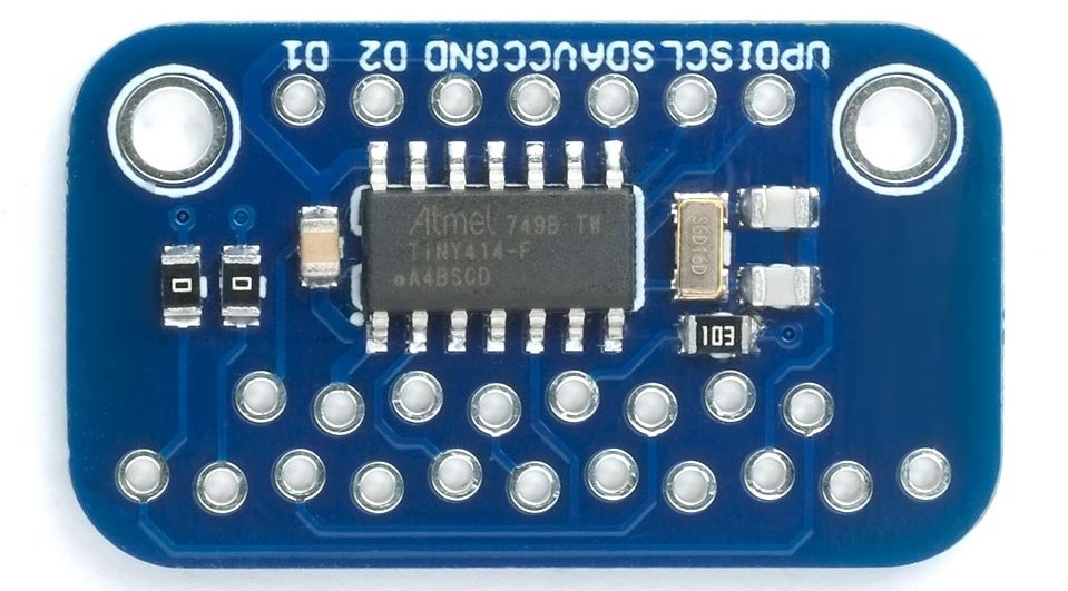
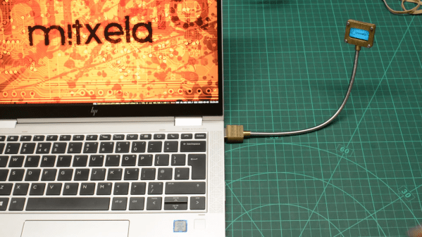
In a blog post from a few years ago, [Peter Molnar] explains in detail how to wire up a physical adapter to add a USB-connected I2C interface to a system. At its core is the ATtiny85 AVR-based MCU, which provides a built-in USB interface, running the I2C-Tiny-USB firmware.
The essential part here is that the MCU shows up to the Linux kernel as an i2c device, requiring the i2c-dev driver to be loaded. After this the I2C device that is connected to the adapter MCU’s I2C bus can be used via the Linux module’s API calls, either directly or via existing drivers. [Peter] found that the BMP280 driver came with Debian Sid, for example.