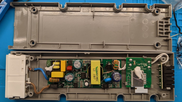
Big Ol’ LED Wall Looks Cool, Can Draw Over 170 Amps

Building giant LED walls comes with a serious set of challenges. Whether they lie in power, cable routing, or just finding a way to clock out data fast enough for all the pixels, it takes some doing to build a decent sized display. [Phill] wanted a statement piece for the office, so rolled up his sleeves and got to work.

The build uses P5 panels, which we’ve seen used before on a smaller scale. Initial testing was done with a Raspberry Pi 3, which started to run out of grunt when the build reached 28 panels. The refresh rate was slow, and anything with motion looked messy. At that point, a dedicated driver was sourced in order to handle the full 48-panel display. Other challenges involved dealing with the huge power requirements – over 170 amps at 5 volts – and building a frame to hold all the panels securely.

The final product is impressive, standing 2 meters wide and 1.2 meters high. Resolution is 384 x 256. With a Mac Mini running video into the display through the off-the-shelf driver, all manner of content is possible. [Phill] even whipped up a Slack channel for users to send GIFs and text messages to the display. Naturally, we’re sure nobody will take advantage of this functionality.

If you’ve got your own giant LED wall, and you’re dying to tell us about it, make sure you get in touch. Video after the break.

Continue reading “Big Ol’ LED Wall Looks Cool, Can Draw Over 170 Amps”

Persistence Of Vision On An Old Fan

Persistence of vision is a fun feature of the human visual system, which allows us to blink a bunch of spinning LEDs at the right time to spell out messages that appear to hang in the air. [TN_Inventor] took a stab at his own POV build, using an old desk fan as a base.

The initial build relied on a rotor made of MDF and some very old-school LEDs. The rotor was heavy and unbalanced, causing issues for the motor, and the dim LEDs weren’t visible in normal daytime conditions. Like any good maker, [TN_Inventor] persevered and iterated the design.

The next revision instead relied on protoboard itself for the rotor, greatly reducing the weight and making it easier to balance. The problem of getting power to a rotating mechanism was sidestepped entirely, with a small lipo battery being mounted on the rotor itself. High-brightness white LEDs were employed, making the effect much more visible. This was helped further thanks to the use of transistors to run the LEDs directly from battery voltage, rather than obeying the current limits of the Arduino Nano’s output pins.

The build presents well, with the final POV board being built into the chassis of an old desk fan. Rather than use the original motor, instead a smaller 12 volt geared device was used, powered separately from the main board. The familiar form factor of the desk fan is a great way to finish the project off, and gives it an interesting industrial aesthetic.

POV builds can go a long way – we’ve even seen volumetric displays built in this way. Video after the break. Continue reading “Persistence Of Vision On An Old Fan”

Flashing LEDs With MIDI, Note By Note

Musical keyboards that light up the correct notes to play have long been touted as a quick and easy way to learn how to play. They’re also fun to look at. [Shootingmaker] has developed a similar concept, with a keyboard lookalike, covered in LEDs (Youtube video, embedded below).

The project consists of a PCB, in which the design of the mask imitates the white and black notes of a piano. This makes it look like a keyboard, but as far as we can tell, it doesn’t actually work as one. All the notes are fitted with APA102 addressable LEDs, under the control of a Teensy 3.2 board, operating in USB-MIDI mode. The Teensy receives MIDI data, and then directs the individual LEDs to flash in different colors based on which MIDI channel fired the note.

It’s a fun way to visualise MIDI data, and we think it would be even more fun combined with a basic synthesis engine to make some noise. We suspect it wouldn’t be too hard to integrate the project into an existing instrument, either. Software is available on Github for those interested in replicating the project. You can use MIDI to control neon lights, too.
Continue reading “Flashing LEDs With MIDI, Note By Note”

Epoxy LED Cube Looks Sleek, And Flashes To The Beat

If there’s one thing that’s universally popular in these polarizing times, it’s colorful glowing objects. LEDs reign supreme in this area, and we’re accustomed to seeing all manner of fun flashy devices hit the tips line. Today is no different, and we’ve been looking at [Modustrial Maker]’s stylish epoxy LED cube.

The build starts with the casting of a black epoxy cube, with a cutout near the top in which the LEDs will be installed. A melamine form is used, with aluminium foil tape, caulk and paste wax to help seal it up. After releasing the cast from the form, there were some unsightly voids which were swiftly dispatched, by trimming the block down with a table saw. With the block cut to size, LED strips were installed, and the light cavity sealed with hot glue before white epoxy was poured in as a diffuser. All that’s left was a simple matter of polishing the cube and installing electronics.

The cube runs from a single-cell LiPo battery, and there’s a wireless power receiver and charging module to keep the power flowing. The cube can be used on most wireless phone chargers, as well as its own dedicated charging base. The LEDs are controlled by an off-the-shelf module, which offers a variety of flashing displays as well as a music-reactive mode.

While the electronics side is done with off-the-shelf parts, the real art in this piece is in the build of the cube. Its glossy, attractive form would look stunning on any coffee table or bedside shelf.

LED cubes are a great rabbit hole to go down on your lunch break. This OpenGL-enabled build is particularly impressive. Video after the break.

Continue reading “Epoxy LED Cube Looks Sleek, And Flashes To The Beat”

The Battery Is Part Of The Art

A work of art is appreciated for its own sake and we will never tire of seeing stunning circuits from microscopic dead-bugs to ornate brass sculptures. We also adore projects that share the tricks to use in our own work. Such is the case with [Jiří Praus] who made some jewelry and shared his templates so we try this out ourselves.

The materials include brass wire, solder, and surface-mount LEDs. Template design expects a 1206 light, so if you step outside that footprint, plan accordingly. The printable templates are intuitive and leverage basic wire jewelry making skills. Some good news is that flashing LEDs are available in that size so you can have an array of blinkenlights that appears random due to drifting circuits. Please be wary with RGB lights or mixing colors because red LEDs generally run at a lower voltage and they will siphon a significant chunk of a coin-cell’s power from a competing green or blue. How else can these be personalized?

[Jiří]’s charms are just the latest of circuits that capture our eyes and tickle our ears.

Building A Googie-Style Sign With The Help Of CNC

The Googie style was a major architectural trend of the post-war period in the United States. It remains popular to throwback to this style, and [Wesley Treat] got the job to create a sign in this vein for a local trailer motel (Youtube link, embedded below).

CNC tools make just about any job easier, and this one is no exception. The smooth curves of the sign were carved out of several sections of PVC sheet, and stacked up to form the body of the sign. These were then sanded, coated in putty, and given a lick of  paint. Steps like these could likely be skipped in the interest of saving time, especially given that few will see those parts once the sign is installed. However, [Wesley] takes pride in his work, and the final piece is all the better for it. It’s also important for the piece to impress the client, not just the public.

The front of the sign is also produced in PVC sheet, and given a coat of paint with brush techniques used to create a faux-wood finish. Vinyl is then applied to the textual and graphical elements in order to create a colored backlit effect. The sign is lit with off-the-shelf LED strips, and the whole assembly is weather sealed to protect it from the elements.

The final product is a beautiful piece, harking back to the classic Googie aesthetic and serving as a testament to [Wesley]’s skills. It’s a great example of how easy it is to create great work with the right tools and the proper attention to detail. It also goes to show how great LEDs are for signage, whether you’re at the beach or the lab. Video after the break.

Continue reading “Building A Googie-Style Sign With The Help Of CNC”

Visualizing LEDs For More Efficient Pin Packing

The archetypal “blink an LED” is a great starter project on any platform, but once the bug takes hold that quickly turns into an exploration of exactly how many LEDs a given microcontroller can drive. And that often leads to Charlieplexing. A quick search yields many copies of The Table describing how many LEDs can be driven by a given number of pins but that’s just the most rudimentary way to describe it. Way back in 2013 [M Rule] developed a clever trick to describe the number of LED matrices which can be driven by a Charlieplexed array of a given size that makes this process much more intuitive. The post may be old, but we promise the method is still fresh.

[M Rule] was specifically looking to drive those big, cheap single color LED matrices which are often used to make scrolling signs and the like. These parts are typically a matrix of LEDs with a row of common cathodes and one of common anodes. Internally they are completely dumb and can be driven by row/column scanning, or any other way a typical matrix can be controlled. The question is, given known matrix sizes, how many can be driven with a a number of Charlieplexed LED drive pins?

The first step is to visualize the 1D array of available pins as a 2D matrix, as seen to the right. Note each numbered pin is the same on the X and Y, thus the black exclusion zone of illegal drive pin combinations slicing across the graph (you can’t drive an LED connected to one pin twice). The trick, if one were to say it resides in a single place, would be titling the axis anode and cathode, representing two “orientations” the drive pins can be put in. With this diagram [M Rule] observed you can simply drop a matrix into the array. If it fits outside the exclusion zone, it can be driven by those pins!

To the left is what this looks like with two 8×8 matrices, one connected between pins 1-8 and 9-16, the other connected between 9-16 and 1-8. This isn’t terribly interesting, but the technique works just as well with single LEDs and any size matrix, including 7-segment displays. Plus as long as an element doesn’t overlap itself it can wrap around the edges leading to some wild visuals, like 14 RGB LEDs on seven pins to the right.

The most extreme examples are pretty exotic. Check out [M Rule]’s post for the crown jewel; 18 pins to drive six 5×7 modules, six 7-segment displays, 12 single LEDs, and 18 buttons!

If this color coded diagram seems familiar, you may be remembering [openmusiclabs]’ excellent diagram describing ways to scan many of buttons. Or our coverage of another trick of matrix topology by [M Rule] from a few weeks ago.