Liquid Damaged MacBook Saved With A Keen Eye

Even among those of us with a penchant for repairing electronics, there are some failures which are generally considered too severe to come back from. A good example is liquid damage in a laptop; with so many components and complex circuits crammed into such a small area, making heads or tails of it once the corrosion sets in can be a real nightmare. Especially in the case of an older laptop, the conventional wisdom is to try and recover your files and then buy a new one.

But as we’ve come to learn, [Jason Gin] is not a man who often finds himself concerned with conventional wisdom. After finding an older MacBook with suspected liquid damage, he decided to see what it would take to restore it to working order. According to a note on the device, the screen was dead, the USB ports were fried, the battery didn’t take a charge, and it wouldn’t boot. No problem then, should be easy.

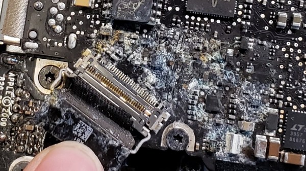
Upon opening up the circa-2012 laptop, [Jason] found the machine to be riddled with corrosion. We’re not just talking surface gunk either. After giving everything a good cleaning with isopropyl alcohol, the true extent of the damage became clear. Not only had traces on the PCB rotted away, but there were many components that were either damaged or missing altogether. Whatever spilled inside this poor Mac was clearly some nasty stuff.

[Jason] used OpenBoardView to pull up schematics and diagrams of the motherboard, and started the arduous task of visually comparing them to his damaged unit. In some areas, the corrosion was so bad he still had trouble locating the correct traces and pads. But with time and effort, he was able to start probing around and seeing what components had actually given up the ghost.

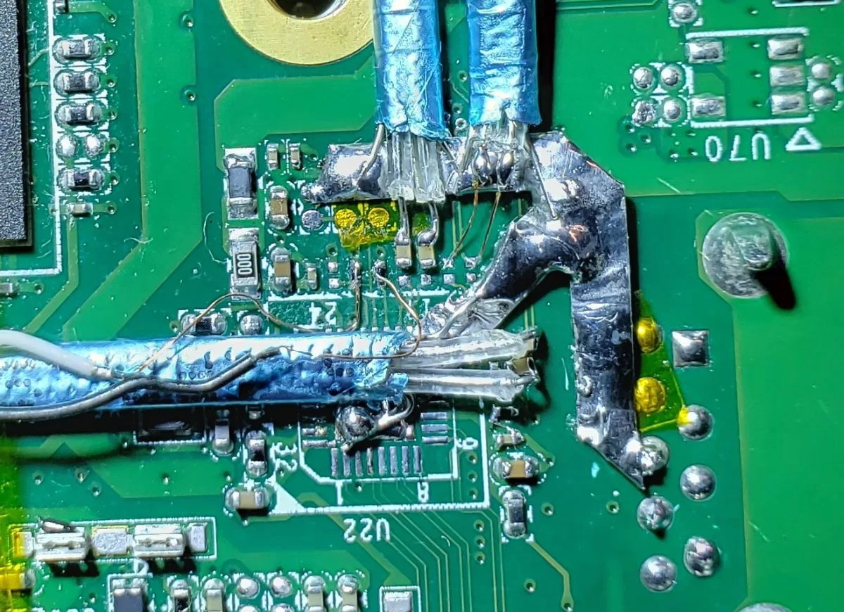
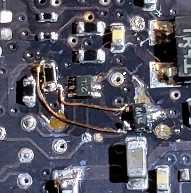
For the USB ports it ended up being a bad 10-microfarad ceramic capacitor, but for the LCD, he ended up having to replace the entire backlight driver IC. The prospect of working on this tiny BGA-25 device might have been enough for some to throw in the towel, but compared to the hand-soldered magnet wire repairs required elsewhere on the board, [Jason] says the installation of the new LP8550 chip was one of the easier aspects of the whole operation.

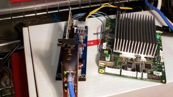
The write-up is a great read if you like a good repair success story, and we especially like the way he documented his diagnosis and resulting work on a per-system basis. It makes it much easier to understand just how many individual fires [Jason] had to put out. But if you’re more interested in feats of steady-handed soldering, check out his recent project to add a PCI-E slot to the Atomic Pi.

How Do You Get PCI-E On The Atomic Pi? Very Carefully.

At this point, you’ve almost certainly heard about the Atomic Pi. The diminutive board that once served as the guts of a failed robot now lives on as a powerful x86 SBC available at a fire sale price. How long you’ll be able to buy them and what happens when the initial stock runs out is another story entirely, but there’s no denying that folks are already out there doing interesting things with them.

One of them is [Jason Gin], who recently completed an epic quest to add a PCI Express (PCI-E) slot to his Atomic Pi. Things didn’t exactly go according to plan and the story arguably has more lows than highs, but in the end he emerged victorious. He doesn’t necessarily recommend you try the same modification on your own Atomic Pi, but he does think this sets the stage for the development of a more refined upgrade down the line.

[Jason] explains that the board’s Ethernet controller was already communicating with the Intel Atom x5-Z8350 SoC over PCI-E, so there was never a question about whether or not the modification was possible. In theory, all you needed to do was disable the Ethernet controller and tack on an external PCI-E socket so you could plug in whatever you want. The trick is pulling off the extremely fine-pitch soldering such a modification required, especially considering how picky the PCI Express standard is.

In practice, it took several attempts with different types of wire before [Jason] was able to get the Atomic Pi to actually recognize something plugged into it. Along the way, he managed to destroy the Ethernet controller somehow, but that wasn’t such a great loss as he planned on disabling it anyway. The final winning combination was 40 gauge magnet wire going between the PCB and a thin SATA cable that is mechanically secured to the board with a piece of metal to keep anything from flexing.

At this point, [Jason] has tested enough external devices connected to his hacked-on port to know the modification has promise. But the way he’s gone about it is obviously a bit temperamental, and far too difficult for most people to accomplish on their own anyway. He’s thinking the way forward might be with a custom PCB that could be aligned over the Ethernet controller and soldered into place, though admits such a project is currently above his comfort level. Any readers interested in a collaboration?

Like most of you, we had high hopes for the Atomic Pi when we first heard about it. But since it became clear the board is the product of another company’s liquidation, there’s been some understandable trepidation in the community. Nobody knows for sure what the future looks like for the Atomic Pi, but that’s clearly not stopping hackers from diving in.

RFID Payment Ring Made From Dissolved Credit Card

RFID payment systems are one of those things that the community seems to be divided on. Some only see the technology as a potential security liability, and will go a far as to disable the RFID chip in their card so that it can’t be read by a would-be attacker. Others think the ease and convenience of paying for goods by tapping their card or smartphone on the register more than makes up for the relatively remote risk of RFID sniffers. Given the time and effort [David Sikes] put into creating this contactless payment ring, we think it’s pretty clear which camp he’s in.

Alright, so the whole ring making part sounds easy enough, but how does one get an RFID chip that’s linked to their account? Easy. Just call the bank and ask them for one. Of course, they won’t just send you out a little RFID chip and antenna to mount in your hacked up project. (If only things were so simple!) But they will send you a new card if you tell them your old one is getting worn out and needs a replacement. All you have to do when it gets there is liberate the electronics without damaging them.

[David] found that an hour or so in an acetone bath was enough to dissolve the plastic and expose the epoxy-encased RFID chip, assuming you scrape the outer layers of the card off first. He notes that you can speed this part of the process up considerably if you know the exact placement and size of the RFID chip; that way you can cut out just the area you’re interested in rather than having to liquefy the whole card.

Once you have your chip, you just need to mount it into a ring. [David] has designed a 3D printable frame (if you’ve got a high-resolution SLA machine, that is) which accepts the chip and a new antenna made from a coil of 38 AWG magnet wire. With the components settled into the printed frame, its off to a silicone mold and the liberal application of epoxy resin to encapsulate the whole thing in a durable shell.

If a ring is not personal enough for you, then the next step is getting the RFID chip implanted directly into your hand. There are even folks at hacker cons who will do that sort of thing for you, if you’re squeamish.

Continue reading “RFID Payment Ring Made From Dissolved Credit Card”

Stepper Motor Mods Improve CNC Flat Coil Winder

Finding just the right off-the-shelf part to complete a project is a satisfying experience – buy it, bolt it on, get on with business. Things don’t always work out so easily, though, which often requires the even more satisfying experience of modifying an existing part to do the job. Modifying a stepper motor by drilling a hole down its shaft probably qualifies for the satisfying mod of the year award.

That’s what [Russ] did to make needed improvements to his CNC flat-coil winder, which uses a modified delta-style 3D-printer to roll fine magnet wire out onto adhesive paper to form beautiful coils of various sizes and shapes. [Russ] has been tweaking his design since we featured it and coming up with better and better coils. While experimenting, the passive roller at the business end proved to be a liability. The problem was that the contact point lagged behind the center axis of the delta, leading to problems with the G-code. [Russ] figured that a new tool with the contact point at the dead center would help. The downside would be having to actively swivel the tool in concert with the X- and Y-axis movements. The video below shows his mods, which include disassembling the NEMA-17 stepper and drilling out the shaft to pass the coil wire. [Russ] also spent some time reversing the rotor in the frame and provided a small preload spring to keep the coil roller in contact with the paper.

A real-time coil winding session starts at the 21:18 mark, and we’ve got to admit it’s oddly soothing to watch. We’re not sure exactly what [Russ] intends to do with these coils, and by his own admission, neither is he. But it’s still pretty cool to see, and the stepper motor mods are a neat trick to keep in mind.

Continue reading “Stepper Motor Mods Improve CNC Flat Coil Winder”

Junkbox Freezer Alarm Keeps Steaks Safe

A fully stocked freezer can be a blessing, but it’s also a disaster waiting to happen. Depending on your tastes, there could be hundreds of dollars worth of food in there, and the only thing between it and the landfill is an uninterrupted supply of electricity. Keep the freezer in an out-of-the-way spot and your food is at even greater risk.

Mitigating that risk is the job of this junkbox power failure alarm. [Derek]’s freezer is in the garage, where GFCI outlets are mandated by code. We’ve covered circuit protection before, including GFCIs, and while they can save a life, they can also trip accidentally and cost you your steaks. [Derek] whipped up a simple alarm based on current flow to the freezer. A home-brew current transformer made from a split ferrite core and some magnet wire is the sensor, and a couple of op-amps and a 555 timer make up the detection and alarm part. And it’s all junk bin stuff — get a load of that Mallory Sonalert from 1983!

Granted, loss of power on a branch circuit is probably one of the less likely failure modes for a freezer, but the principles are generally applicable and worth knowing. And hats off to [Derek] for eschewing the microcontroller and rolling this old school. Not that there’s anything wrong with IoT fridge and freezer alarms.

Continue reading “Junkbox Freezer Alarm Keeps Steaks Safe”

Giant Stepper Motor Gets You Up To Speed On Theory

Few hackers have trouble understanding basic electric motors. We’ve all taken apart something that has a permanent magnet DC motor in it and hooked up its two leads to a battery to make it spin. Reverse the polarity, reverse the spin; remove the power, stop the spin. Stepper motors (and their close cousins, brushless DC motors) are a little tougher to grok, though, especially for the beginner. But with a giant 3D printed stepper motor, [Proto G] has made getting your head around electronically commutated motors a little easier.

While we’ve seen 3D printed stepper motors before, the size and simple layout of this one really lends to understanding the theory. With a 3D-printed frame, coils wound on nails, and rare-earth magnets glued to a rotor, this is an approachable build that lays the internals of a stepper motor out for all to see and understand. You can easily watch how the rotor lines up as the various coils are energized in a circular pattern, although it might be more revealing to include bi-color LEDs to indicate which coils are energized and what the polarity is. Those would be especially helpful demonstrating the concept of half-stepping. We’d also like to see more detail on the controller electronics, although admittedly all the video-worthy action is in the motor itself.

Continue reading “Giant Stepper Motor Gets You Up To Speed On Theory”

tweeter

Repairing Burnt Speakers With A Steady Hand

[Martin] seems to have a knack for locating lightly damaged second-hand audio gear. Over the years he’s collected various types of gear and made various repairs. His most recent project involved fixing two broken tweeter speakers.

He first he needed to test the tweeters. He had to remove them from the speaker cabinet in order to gain easier access to them. The multimeter showed them as an open-circuit, indicating that they had likely been burned. This is an issue he’s seen in the past with this brand of speaker. When too much power is pumped through the speaker, the tiny magnet wire inside over heats and burns out similar to a fuse.

The voice coil itself was bathing in an oily fluid. The idea is to help keep the coil cool so it doesn’t burn out. With that in mind, the thin wire would have likely burned somewhere outside of the cooling fluid. It turned out that it had become damaged just barely outside of the coil. [Martin] used a sharp blade to sever the connection to the coil. He then made a simple repair by soldering the magnet wire back in place using a very thin iron. We’ve seen similar work before with headphone cables.

He repeated this process on the second tweeter and put everything back together. It worked good as new. This may have ultimately been a very simple fix, but considering the amount of money [Martin] saved on these speakers, it was well worth the minimal effort.