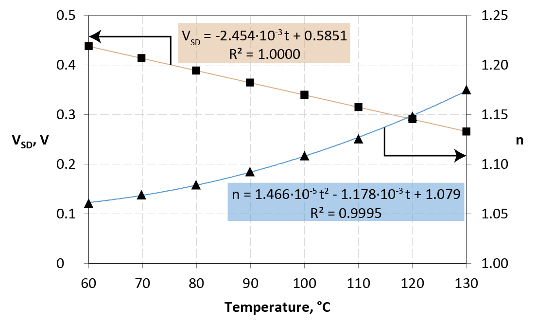
Quick: What’s the forward voltage drop on a conducting diode? If you answered something like 0.6 to 0.7 V, you get a passing grade, but you’re going to have to read on. If you answered 
T0 and k are device-specific constants to be determined experimentally, you get a gold Jolly Wrencher.
 [Jakub] earned his Wrencher, and then some. Because not only did he use the above equation to make a temperature sensor, he did so with a diode that you might have even forgotten that you have on hand — the one inside the silicon of a MOSFET — the intrinsic body diode.
[Jakub]’s main project is an Arduino-controlled electronic load that he calls the MightWatt, and a beefy power MOSFET is used as the variable resistance element. When it’s pulling 20 or 30 A, it gets hot. How hot exactly is hard to measure without a temperature sensor, and the best possible temperature sensor would be one that was built into the MOSFET’s die itself.
There’s a bunch of detail in his write-up about how he switches the load in and out to measure the forward drop, and how he calibrates the whole thing. It’s technical, but give it a read, it’s good stuff. This is a great trick to have up your sleeve.
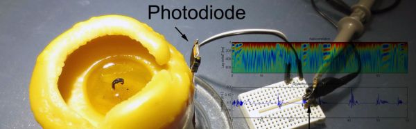
And if you’re in the mood for more stupid diode tricks, we recommend using them as solar cells or just stringing a bunch of them together to make a thermal camera.