Review: Microchip Curiosity Is A Gorgeous New 8-bit Dev Board

Microchip has unveiled a new dev board called the Curiosity Development Board. I had my first look at this at Bay Area Maker Faire back in May but was asked not to publicize the hardware since it wasn’t officially released yet. Yesterday I got my hands on one of the first “pilot program” demo units and spent some time working with it.

I requested a sample board out of my own curiosity. As you may know, Microchip is one of the sponsors of the 2015 Hackaday Prize, but that partnership does not include this review. However, since we do have this relationship we asked if they would throw in a few extra boards that we could give away and they obliged. More about that at the end of the post.

Continue reading “Review: Microchip Curiosity Is A Gorgeous New 8-bit Dev Board”

Get Your Kicks With This New PIC Development Board

While development boards for micro controllers are nothing ground breaking, they can be expensive, and often times overkill for what you’re doing when they try to put everything you might use … including the kitchen sink. when [Brian] noticed his projects were starting to use Microchip PIC24 more and more, the time came to have a dev board on hand. 

top-view
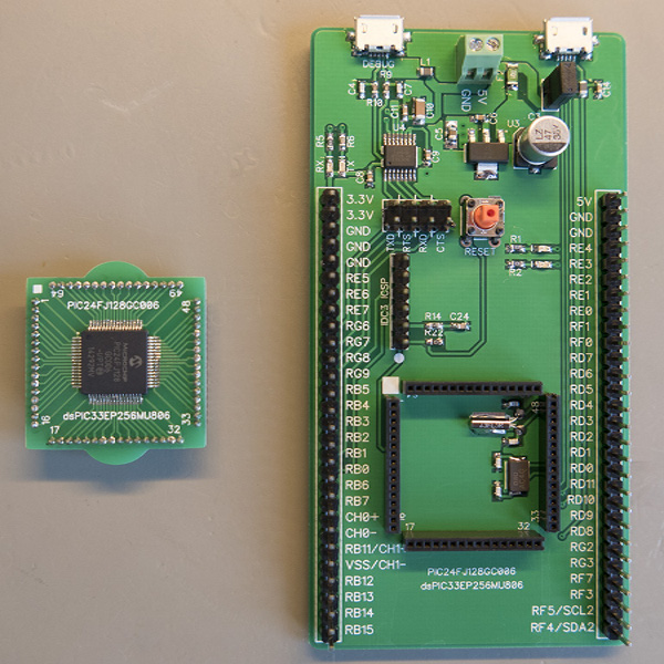
The result is a small board with breakouts for USB, UART (via FTDI), of course tons of GPIO pins, and a socket which mates with a daughter board to swap out either a PIC24FJ128GC006, or a DSPIC33EP256MU806, with the potential for more. Also packed on the board is a power regulator system and dual crystals allowing full speed operation or power sipping modes.

Schematics and PCB layout are available (in Diptrace format) along with a board template file to use with MPLAB on github.com. Once you have everything together you will need a PIC programmer, [Brian] is using a trusty Microchip MPLAB ICD 3 programmer, but naturally, others are available.

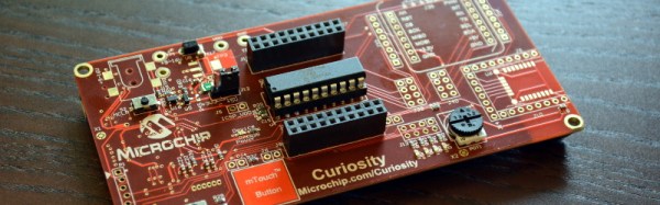
Microchip recently announced a new development board of their own for the PIC16F series. The Curiosity board has built-in support for programming and debugging (no chipKIT needed). The engineer who designed that board, [John Mouton] is going to join us on July 30th for a live chat about the design process. We’re also going to be giving away some of the first boards to come off the production line… more about that this coming week.

50 Winners Using Microchip Parts

For the last few weeks we’ve been celebrating builds that use parts from our manufacturer sponsors of the 2015 Hackaday Prize. Today we are happy to announce 50 winners who used Microchip parts in their builds. Making the cut is one thing, but rising to the top is another. These builds show off some amazing work from those who entered them. In addition to the prizes which we’ll be sending out, we’d like these projects to receive the recognition they deserve. Please take the time to click through to the projects, explore what has been accomplished, and leave congratulations a comment on the project page.

Still Time to Win!

We’re far from the end of the line. We’ll be giving roughly $17,000 more in prizes before the entry round closes in the middle of August. Enter your build now for a chance in these weekly contests! This week we’re looking for things that move in our Wings, Wheels, and Propellers Contest.

One voter will win $1000 from the Hackaday Store this week as well! Anyone is welcome to vote in Astronaut or Not. Vote Now! The drawing is tomorrow afternoon.

Continue reading “50 Winners Using Microchip Parts”

Temperature Logger

Logging Engine Temperature For RC Models

[Rui] enjoys his remote-controlled helicopter hobby and he was looking for a way to better track the temperature of the helicopter’s engine. According to [Rui], engine temperature can affect the performance of the craft, as well as the longevity and durability of the engine. He ended up building his own temperature logger from scratch.

The data logger runs from a PIC 16F88 microcontroller mounted to a circuit board. The PIC reads temperature data from a LM35 temperature sensor. This device can detect temperatures up to 140 degrees Celsius. The temperature sensor is mounted to the engine using Arctic Alumina Silver paste. The paste acts as a glue, holding the sensor in place. The circuit also contains a Microchip 24LC512 EEPROM separated into four blocks. This allows [Rui] to easily make four separate data recordings. His data logger can record up to 15 minutes of data per memory block at two samples per second.

Three buttons on the circuit allow for control over the memory. One button selects which of the four memory banks are being accessed. A second button changes modes between reading, writing, and erasing. The third button actually starts or stops the reading or writing action. The board contains an RS232 port to read the data onto a computer. The circuit is powered via two AA batteries. Combined, these batteries don’t put out the full 5V required for the circuit. [Rui] included a DC-DC converter in order to boost the voltage up high enough.

Remote Tester

A Simple Circuit For Testing Infrared Remote Controls

Every now and then a remote control acts up. Maybe you are trying to change the channel on your television and it’s just not working. A quick way to determine if the remote control is still working is by using a cell phone camera to try to see if the IR LED is still lighting up. That can work sometimes but not always. [Rui] had this problem and he decided to build his own circuit to make it easier to tell if a remote control was having problems.

The circuit uses a Vishay V34836 infrared receiver to pick up the invisible signals that are sent from a remote control. A Microchip 12F683 processes the data and has two main output modes. If the remote control is receiving data continuously, then a green LED lights up to indicate that the remote is functioning properly. If some data is received but not in a continuous stream, then a yellow LED lights up instead. This indicates that the batteries on the remote need to be replaced.

The circuit also includes a red LED as a power indicator as well as RS232 output of the actual received data. The PCB was cut using a milling machine. It’s glued to the top of a dual AAA battery holder, which provides plenty of current to run the circuit.

Hacking A Wireless AC Power Outlet

It’s always nice to see hackers pick up stuff headed for the landfill and put it back in action with a quick repair and upgrade. [Septillion] found a wireless remote controlled AC outlet in the junk bin and decided to do just that. A nice spin-off of such hacks is that we end up learning a lot about how things work.

His initial tests showed that the AC outlet and its remote could be revived, so he set about exploring its guts. These remote AC outlets consist of an encoder chip on the remote and a corresponding decoder chip on the outlet, working at 433MHz.  Since the various brands in use have a slightly different logic, it needed some rework to make them compatible. The transmit remote was a quick fix – changing the DIP switch selected address bits from being pulled low to high and swapping the On and Off buttons to make it compatible with the other outlets.

Working on the AC outlet requires far more care and safety. The 230V AC is dropped down using a series capacitor, so the circuit is “hot” to touch. Working on it when it is powered up requires extreme caution. A quick fix would have been to make the changes to the address bits and the On/Off buttons to reflect the changes already made in the remote transmitter. Instead, he breadboarded a small circuit around the PIC12F629 microcontroller to take care of the data and address control. Besides, he wanted to be able to manually switch the AC outlet. The relay control from the decoder was routed via the microcontroller. This allowed either the decoder or the local manual switch from controlling the relay. Adding the PIC also allowed him to program in a few additional modes of operation, including one which doubled the number of outlets he could switch with one remote.

Hackaday Prize Entry: A Two Component Temperature Sensor

Here’s a design challenge for you: make a temperature sensor for any computer. If you’re an exceptionally clever smart ass, you’ll probably write some code to report the CPU temps. Others who take the exercise seriously will probably build something with a 1-wire temp sensor, a microcontroller, and all the hardware required to do that.

[Michael] had a better idea. He did it with just two components. One of those components is a USB connector.

The only reason is project could be created is a rather new part from Microchip, the PIC16F1455. This microcontroller doesn’t require a crystal, can do USB without any additional parts, and has an integrated temperature sensor. [Michael] whipped up a project to set up a USB CDC serial device, read the temperature with the ADC (thanks to a very helpful app note), and sends the temperature to a computer once a second.

Despite being built out of only two components, this could actually be a useful device. The PIC is a USB serial device, and this can be used with any computer made in the past 15 or so years. It would hardly take any code at all to read the temperature with another program, and it’s a very inexpensive build. We have to give style points for soldering a microcontroller directly to a USB connector, too.


The 2015 Hackaday Prize is sponsored by: