One of the perks of using older hardware is its comparative simplicity and extensive documentation. After years or decades of users programming on a platform, the amount of knowledge available for it can become extensive. This is certainly the case with the 6502 microprocessor, used in old Apple computers and some video game systems from the ’80s. The extensive amount of resources available make it a prime candidate in exploring various programming languages, and their advantages and disadvantage.
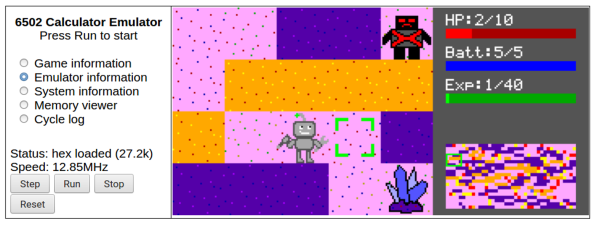
This project looks into those differences using a robot game, which has been programmed four different ways in three languages. [Joey] created the game in Python first and then began to port it to the 65C02, a CMOS variant of the 6502. The first iteration is its assembly language, and then a second iteration with optimized assembly code. From there, he ports it to C and then finally to Forth. Each version of the game is available to play in a browser using an emulator to run the 6502 hardware.
Since the games run in the browser, other tools are available to examine the way the game runs in each language. Registers can be viewed in real time, as well as the values stored in the memory. It’s an interesting look at an old piece of hardware and of its inner workings. For an even deeper dive into the 6502, it’s possible to build a working computer on breadboards using one.