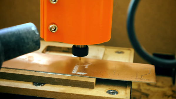
Yes, you can whip up a design for a printed circuit board, send it out to one of the many fab houses, and receive a finished, completed board in a week or two. There are quick-turn assembly houses that will manufacture a circuit board and populate it for you. But sometimes you need a board now, and that’s when we get into home PCB fabrication. You can do this with either etching or milling, but [Renzo] has a great solution. He built a 3D printed milling machine that will make a printed circuit board.
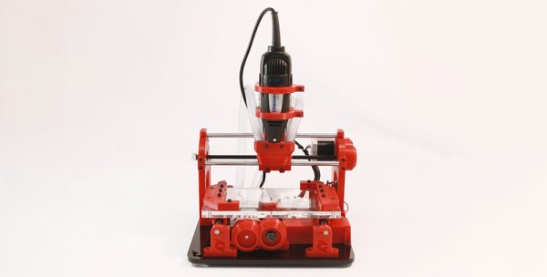
The design of this tiny micro mill is based on a handheld rotary tool, also called a Dremel, but that’s like Kleenex, so just buy a Proxxon. This mill is designed with 3D printed T-track and constructed with linear bearings on smooth rods with standard NEMA 17 stepper motors and herringbone gears for little to no backlash. There is quite a bit going on here, but lucky for us [Renzo] has a video tutorial of the entire build process available for viewing below.
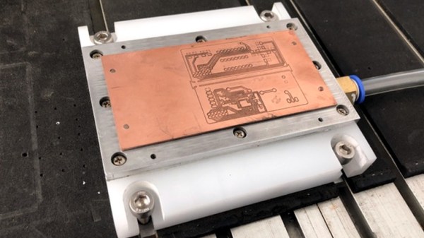
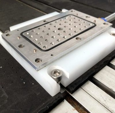
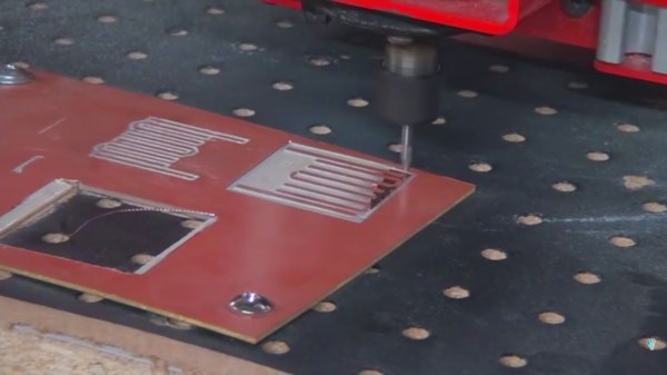
We’ve previously seen some of [Renzo]’s previous efforts in homemade PCB fabrication, up to and including applying green soldermask with the help of Fritzing. This is good, very good, and the only thing that really separates this from manufactured PCBs is the lack of plated through holes. That’s just a bit of graphite and electroplating away, and we’re looking forward to [Renzo]’s further adventures in making PCBs at home.

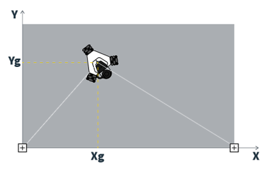 What really caught our eye is the Goliath’s unique positioning system. While most CNC machines have the luxury of end-stops or servomotors capable of precise positional control, the Goliath has two “base sensors” that are tethered to the top of the machine and mounted to the edge of the workpiece. Each sensor connects to the host computer via USB and uses vaguely termed “Radio Frequency technology” that provides a 100Hz update for the machine’s coordinate system. This setup is sure to beat out dead-reckoning for positional awareness, but details are scant on how it precisely operates. We’d love to know more if you’ve used a similar setup for local positioning as this is still a daunting task for indoor robots.


