Buying surplus equipment lends a frisson of excitement as you eagerly await the package or crate containing your purchase. Did you buy a hidden treasure, or has some shyster succeeded in unloading a pile of garbage onto you, their mark? [Professor Churls] shelled out $49.99 for a military surplus bomb hoist which definitely falls into the former category. His teardown reveals it to be a beautifully over-engineered piece of Cold-War-era American hardware.
As the package with its extremely heavy contents is first inspected, he reminds us just what a bomb hoist does, it is clipped to an aircraft by ground crew and serves as a small but extremely powerful crane to lift up to a 6000-pound piece of ordnance onto the wing pylon of an aircraft. This particular example dates from the 1960s, and features a 28-volt DC motor coupled to a bulky gearbox assembly on a swivel mount for attachment.
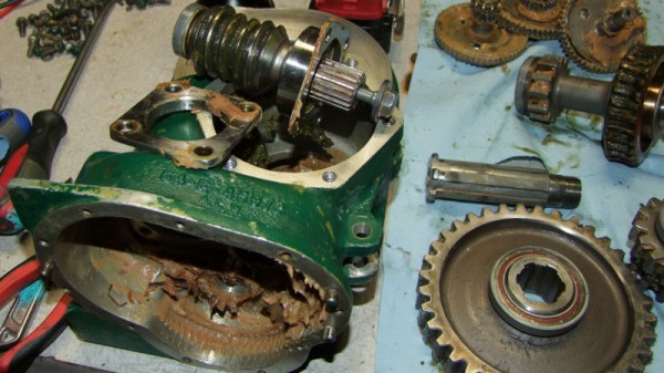
His teardown is extremely detailed, but such is the engineering and complexity of the device you’ll want to read every part of it. The motor is a fairly traditional separately-excited brushed DC design such as you’d expect from that era, but with unusual features such as brushes on pivots rather than a slide. The multiple sets of gears are packed in aged and phenolic-smelling grease, and have unusual features such as stub-form teeth for high torque at low durations. There is even an entirely separate gear train for the hex drive provided so that crews could keep the bombers rolling even when the power was out.
He leaves us with the tantalising information that there is a project awaiting this device, but doesn’t tell us what that might be. We hope we’ll get to see it, whatever it is. Meanwhile it’s great to see that this kind of item can still be found from military surplus suppliers, where this is being written they have degenerated into little more than stockists of camouflage-printed camping gear. Our colleague [Brandon Dunson] lamented in 2015 on the slow decline of the electronic surplus business in his location.