We often marvel at the many things a 555 can do. But [Zafer Yildiz] shows us that it can even take the place of a PCB. You’ll see what we mean in the video below. The timer relay circuit is built “dead bug” style with the 555 leads bent out to provide wiring terminals.
Honestly, these kinds of circuits are fun, but we would be reticent to use this type of construction for anything that had to survive in the real world. Solder joints aren’t known for being mechanically stable, so this is good for experiments, but maybe not something you want to do all the time.
For all that “should have used a 555” is a bit of a meme around here, there’s some truth to it. The humble 555 is a wonderful tool in the right hands. That’s why it’s wonderful to see this all-analog stylus synth project by EE student [DarcyJ] bringing the 555 out for the new generation.
The project is heavily inspired by the vintage stylophone, but has some neat tweaks. A capacitor bank means multiple octaves are available, and using a ladder of trim pots instead of fixed resistors makes every note tunable. [Darcy] of course included the vibrato function of the original, but no, he did not use a 555 for that, too. He used an RC oscillator. He put a trim pot on that, too, to control the depth of vibrato, which we don’t recall seeing on the original stylophone.
The writeup is very high quality and could be recommended to anyone just getting started in analog (or analogue) electronics– not only does [Darcy] explain his design process, he also shows his pratfalls and mistakes, like in the various revisions he went through before discovering the push-pull amplifier that ultimately powers the speaker.
Since each circuit is separately laid out and indicated on the PCB [Darcy] designed in KiCad for this project. Between that and everything being thru-hole, it seems like [Darcy] has the makings of a lovely training kit. If you’re interested in rolling your own, the files are on GitHub under a CERN-OHL-S v2 license, and don’t forget to check out the demo video embedded below to hear it in action.
Although commonly referred to as a ‘timer IC’, the venerable NE555 and derivatives are in fact not timer ICs. This perhaps controversial statement is the open door that gets kicked in by [PKAE Electronics] over at YouTube, as he explains with excellent diagrams and simulations how exactly these ICs work, and what it takes to make it actually do timer things. For anyone who has ever used one of these chips there is probably nothing too mind-blowing, but it’s an infinitely better way to wrap your way around an NE555 and kin than a datasheet.
At its core, the 555 contains three 5 kOhm resistors as a voltage divider, which has been incorrectly postulated to be the source of the chip’s name. This voltage divider controls two comparators, which in turn control an SR flipflop. These comparators are used for the voltage trigger and threshold inputs, which in turn toggle the flipflop, respectively setting and resetting it. This by itself just means that the 555 can be used as a threshold detector, with settable control voltage. How a 555 becomes a timer is when the discharge, trigger and threshold pins are combined with external resistors and a capacitor, which creates a smooth square wave on the 555’s output pin.
There are many ways to make basic components into an oscillator of some type, but the 555 is a great choice when you want something more refined that doesn’t involve using an entire MCU. That said, there’s far more that the 555 can be used for, as [PKAE] alludes to, and we hope that he makes more excellent videos on these applications.
Some design choices on manufacturing equipment really leave you scratching your head for a while, as recently happened to [Chris Cecil] when the belt on a reflow oven’s conveyer snapped. Although the solution seems simple enough, getting a new belt on the thing would involve essentially taking the entire machine apart, before reassembling it again. Thus the frayed belt went through the oven over and over until during a recent production run of Smoothieboard controller boards until [Chris] heard a funny noise and the conveyer ground to a halt.
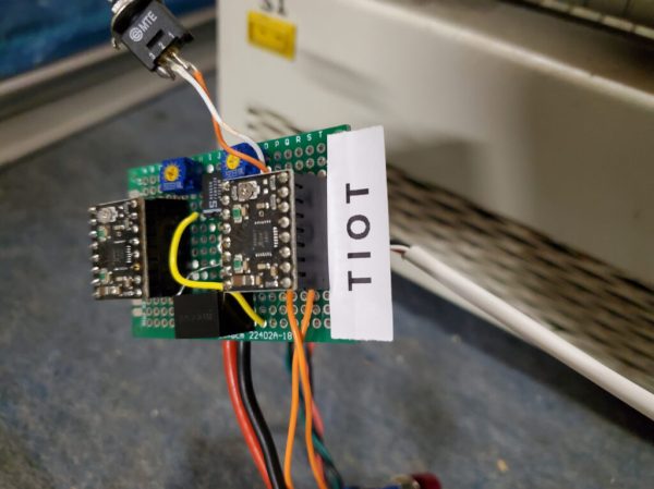
Moving the conveyer by hand kind of worked, but with a more permanent fix urgently needed to finish the production run, two stepper motors took the place of the belt, which just left driving these steppers to keep the conveyer moving in sync. Lacking a simple Arduino board to toss at it, and with a Smoothieboard being absolute overkill, [Chris] figured that a humble NE555 timer IC ought to do the job just as well.
Using a project on Hackaday.io by [KushagraK7] as the starting point, and a 1992-vintage NE555 IC harvested from an old project, [Chris] managed to put together a basic stepper driver that uses the NE555 to provide the timing signal. In addition to restoring basic functionality like starting and stopping the conveyer belt, [Chris] added a new feature with the reversing of the conveyer direction. Along with some cobbled together components to physically rotate the conveyer’s two rollers, it restored the reflow oven to working condition.
And one day the prototyped driver board will be updated to a proper PCB. It’s only temporary, after all :)
It has become a bit of a running joke in the Hackaday community to suggest that a project could or should have been done with a 555 timer. [Tim] has rather taken this to heart with his latest Electronic Dice project, which uses three of the venerable devices.
If three seems like a lot of 555s to make an electronic die, then it may be worth considering that the last time we shared his project he was using 22 of them! Since then, [Tim] has been busy optimising his design, whilst keeping within the constraints of an old-school through-hole soldering kit.
Maybe the most surprising thing about this project is the purpose to which the NE555 devices are pressed. Rather than using them for their famous oscillation properties, they are in actual fact just being used as Schmitt Triggers to clean up the three-phase ring oscillator that is constructed from discrete transistors and passives.
Simulation trace of the three-phase ring oscillator before Scmitt Trigger stages
The ring oscillator cleverly produces three phase-shifted square waves such that a binary combination of the three phases offers six unique states. Six being the perfect number for a dice throw, all that then remains is to figure out which LEDs need to be switched on in which state and wire them up accordingly.
To “roll” the dice, a push-button powers up the oscillator, and stops it again when it is released, displaying the random end-state on the LEDs.
It can be fun to see what can be done using old technology, and educational to try to optimise a design down to the fewest parts possible.
[Tim]’s earlier project is here if you want to see how the design has evolved. The documentation on both of these iterations is excellent and well worth a read.
One of the most common clichés around here is that a piece of equipment chosen for a project is always too advanced. If a Raspberry Pi was used, someone will say they should have used an Arduino. If they use an Arduino, it should have been an ATtiny. And of course, if an ATtiny was used, there should have simply been a 555 timer. This time, however, [Tim] decided to actually show how this can be done by removing some of the integrated circuits from an electronic dice and relying entirely on the 555 timer for his build.
The electronic dice that [Tim] has on hand makes use of two main ICs: a NE555 and a CD4017 which is a decade counter/divider used for cycling through states. In order to bring the 555 to the forefront of this build, he scraps the CD4017 and adds an array of 555 timers. These are used to generate the clock signals necessary for this build but can also be arranged to form logic circuits. This comes at a great cost, however. The 555 chips take up an unnecessarily large area on the PCB (even though these are small surface-mount chips), consume an incredible amount of power, and are very slow. That’s fine for an electronic dice-rolling machine like this one, but that’s probably where [Tim] will leave this idea.
If you spend enough time trolling eBay for interesting electronic devices to take apart, you’re bound to start seeing suggestions for some questionable gadgets. Which is how I recently became aware of these tiny GPS jammers that plug directly into an automotive 12 V outlet. Shipped to your door for under $10 USD, it seemed like a perfect device to rip open in the name of science.
Now, you might be wondering what legitimate uses such a device might have. Well, as far as I’m aware, there aren’t any. The only reason you’d want to jam GPS signals in and around a vehicle is if you’re trying to get away with something you shouldn’t be doing. Maybe you’re out driving a tracked company car and want to enjoy a quick two hour nap in a parking lot, or perhaps you’re looking to disable the integrated GPS on the car you just stole long enough for you to take it to the chop shop. You know, as one does.
But we won’t dwell on the potentially nefarious reasons that this device exists. Hackers have never been too choosy about the devices they investigate and experiment with, and there’s no reason we should start now. Instead, let’s take this piece of gray-area hardware for a test drive and see what makes it tick.