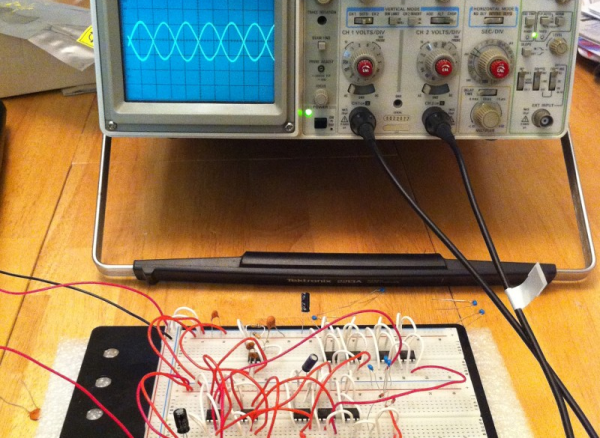
Hardly a week goes by that we don’t post a project where at least one commenter will lament that the hacker could have just used a 555. [Peter Monta] clearly gets that point of view. For a 555 design contest, he created both digital logic gates and an op amp, all using 555 chips. We can’t quite imagine the post apocalyptic world where the only surviving electronic components are 555 chips, but if that day were to come, [Peter] is your guy.
Using the internal structure of the 555, [Peter] formed a basic logic gate, an inverter, latches, and more. He also composed things like counters and seven-segment decoders. He had a very simple 4-bit CPU design in Verilog that he was going to attempt until he realized it would map into almost 400 chips (half of that if you’d use a dual 555, but still). If you built this successfully, we would probably post it, by the way. You can see a video of the digital logic counter, below.
Everyone knows how to convert from Celsius to Fahrenheit, right? On a digital thermometer you just flick the little switch, on a weather app you change the settings, or if worse comes to worse, you let Google do the math for you. But what if you want to solve the problem the old-fashioned way? Then you pull out a few op amps and do your conversions analog style.
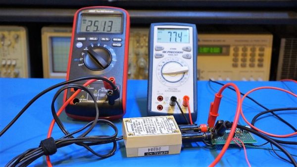
We’ve seen before how simple op amp circuits can do basic math, and the equation that [Kerry Wong] wants to solve is even simpler. Recalling the old Tf = 9/5·Tc + 32 formula (and putting aside the relative merits of metric versus traditional units; we’ve had enough of that argument already), [Kerry] walks us through a simple dual op amp circuit to convert the 1 mV/°C output of a thermocouple module to 1 mV/°F. The scaling is taken care of by a non-inverting amplifier with resistors chosen to provide a gain of 1.8, while the offset is handled by a differential amplifier that adds 32 mV to the scaled input. Strategically placed trimmers allow [Kerry] to tweak the circuit to give just the right conversion.
For jobs like this, it’s tempting to just use an analog input on an Arduino and take care of conversions in code. But it’s nice to know how to do it old school, too, and hats off to [Kerry] for showing us the details.
A few years ago, there was a stir about a new fundamental component called a memristor. That wasn’t the first time a new component type was theorized though. In 1948 [Bernard Tellegen] postulated the gyrator. While you can’t buy one as a component, you can build one using other components. In fact, they are very necessary for some types of design. Put simply, a gyrator is a two-terminal device that inverts the current-voltage characteristic of an electrical component. Therefore, you can use a gyrator to convert a capacitor into an inductor or vice versa.
Keep in mind, the conversion is simply the electrical properties. Normally, current leads voltage in a capacitor and lags it in an inductor, and that’s what a gyrator changes. If you use a gyrator and a capacitor to make a virtual inductor, that inductor won’t magnetically couple to another inductor, real or simulated. There’s no magnetic field to do so. You also don’t get big voltage spikes caused by back EMF, which depending on your application could be a plus or a minus. But if you need an ungainly inductor in a circuit for its phase response, a gyrator may be just the ticket.
Can you buy a working radar module for $12? As it turns out, you can. But can you make it output useful information? According to [Mathieu], the answer is also yes, but only if you ignore the datasheet circuit and build this amplification circuit for your dirt cheap Doppler module.
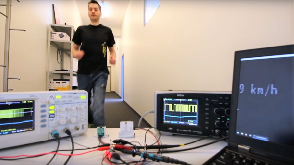
The module in question is a CDM324 24-GHz board that’s currently listing for $12 on Amazon. It’s the K-band cousin of the X-band HB100 used by [Mathieu] in a project we covered a few years back, but thanks to the shorter wavelength the module is much smaller — just an inch square. [Mathieu] discovered that the new module suffered from the same misleading amplifier circuit in the datasheet. After making some adjustments, a two-stage amp was designed and executed on a board that piggybacks on the module with a 3D-printed bracket.
Frequency output is proportional to the velocity of the detected object; the maximum speed for the sensor is only 14.5 mph (22.7 km/h), so don’t expect to be tracking anything too fast. Nevertheless, this could be a handy sensor, and it’s definitely a solid lesson in design. Still, if your tastes run more toward using this module on the 1.25-cm ham band, have a look at this HB100-based 3-cm band radio.
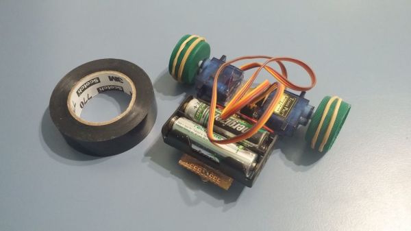
Line Followers are a tried-and-true type of robot; both hardware and software need to be doing their job in harmony in order to be successful at a clearly defined physical task. But robots don’t always have microcontrollers and software, as [Mati_DIY]’s zero programming analog line follower demonstrates.
For readers used to seeing a Raspberry Pi or Arduino in almost everything, an analog robot whose “programming” exists only as a harmony between its discrete parts can be an eye-opener as well as an accessible project. A video of the robot in action is embedded below.
[Mati_DIY]’s design uses two CNY70 reflective sensors (which are essentially infrared emitter/phototransistor pairs) and an LM358 dual op-amp. Together, the sensors act as two near-sighted eyes. By using the output of each sensor to drive a motor via a transistor, the presence or absence of the black line is directly and immediately reflected by the motion of the attached motor. The more black the sensor sees, the more the motor turns. Electrically, that’s all that happens; but by attaching the right sensor to the left motor and the left sensor to the right motor, you get a robot that always tries to keep the black line centered under the sensors. Playing with the spacing of the motors and sensors further tweaks the performance.
There comes a time in every electronic designer’s life when, whether they know it or not, they need an analog filter in their design. If you’re coming from a digital background, where everything is nice and numeric, the harsh reality of continuous voltages can be a bit of a shock. But if you’re taking input from, or sending output to the big analog world out there, it pays to at least think about the frequency-domain properties of the signal, and maybe even do something about them.
Designing an analog filter to fit your needs can be a bit of a daunting task: there are many factors that you’re going to need to consider, and they all interact. It’s easy to get lost. We’re going to simplify this as much as possible by instead focusing on a few common applications and building up the simplest possible filters that work well for them.
Today, we’re going to consider the lowpass filter, and specifically a Sallen-Key filter with Butterworth characteristics and a second-order rolloff. Sound like word salad? We’ll fix that up right away, because this is probably the single most important filter to have in your analog toolbox for two very common use cases: pulse-width modulated (PWM) output and analog-to-digital conversion (ADC) input.
There is an old saying: “In theory, theory and practice are the same. In practice, they are not.” We spend our time drawing on paper or a computer screen, perfect wires, ideal resistors, and flawless waveforms. Alas, the real world is not so kind. Components have all kinds of nasty parasitic effects and no signal looks like it does in the pages of a text book.
Consider the following problem. You have a sine wave input coming in that varies between 0 V and 5 V. You want to convert it to a square wave that is high when the sine wave is over 2.5 V. Simple, right? You could use a CMOS logic gate or a comparator. In theory…
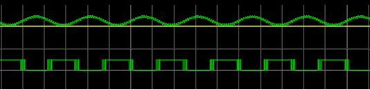
The problem is, the sine wave isn’t perfect. And the other components will have little issues. If you’ve ever tried this in real life, you’ll find that when the sine wave is right at the 2.5 V mark the output will probably swing back and forth before it settles down. This is exacerbated by any noise or stretching in the sine wave. You will wind up with something like this:
Notice how the edges of the square wave are a bit fat? That’s the output switching rapidly back and forth right at the comparator’s threshold.
Hysteresis
The answer is to not set the threshold at 2.5 V, or any other single value. Instead, impose a range outside of which it will switch, switching low when it leaves the low end of the range, and high when it exceeds the high end. That is, you want to introduce hysteresis. For example, if the 0 to 1 shift occurs at, say, 1.9 V and the 1 to 0 switch is at 0.5 V, you’ll get a clean signal because once a 0 to 1 transition happens at 1.9 V, it’ll take a lot of noise to flip it all the way back below 0.5 V.
You see the same effect in temperature controllers, for example. If you have a heater and a thermal probe, you can’t easily set a 100 degree set point by turning the heater off right away when you reach 100 and then back on again at 99.9999. You will usually use hysteresis in this case, too (if not something more sophisticated like a PID). You might turn the heater off at 99 degrees and back on again at 95 degrees, for example. Indeed, your thermostat at home is a prime example of a system with hysteresis — it has a dead-band of a few degrees so that it’s not constantly turning itself on and off.
Schmitt Triggers and How to Get One
A Schmitt Trigger is basically a comparator with hysteresis. Instead of comparing the incoming voltage with VCC / 2, as a simple comparator would, it incorporates a dead band to ensure that logic-level transitions occur only once even in the presence of a noisy input signal.
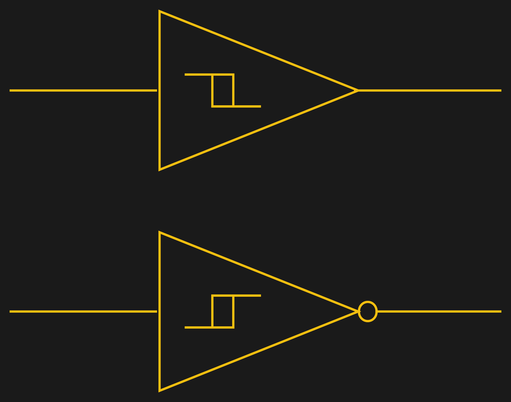
Assuming you want a Schmitt trigger in a circuit, you have plenty of options. There are ICs like the 74HC14 that include six (inverting) Schmitt triggers. On a schematic, each gate is represented by one of the symbols to the right; the little mark in the box is the hysteresis curve, and the little bubble on the output indicates logical negation when it’s an inverter.
You can also make them yourself out of transistors or even a 555 chip. But the easiest way by far is to introduce some feedback into a plain op amp comparator circuit.
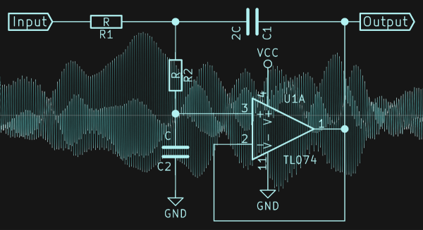
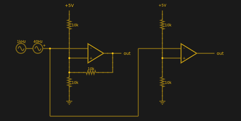
Below are two op amps, one with some positive feedback to make it act like a Schmitt trigger. The other is just a plain comparator. You can simulate the design online.
If you haven’t analyzed many op amp circuits, this is a good one to try. First, imagine an op amp has the following characteristics:
The inputs are totally open.
The output will do whatever it takes to make the inputs voltages the same, up to the power supply rails.
Neither of these are totally true (theory vs. practice, again), but they are close enough.
The comparator on the right doesn’t load the inputs at all, because the input pins are open circuit, and the output swings to either 0 V or 5 V to try, unsuccessfully, to make the inputs match. It can’t change the inputs because there is no feedback, but it does make a fine comparator. The voltage divider on the + pin provides a reference voltage. Anything under that voltage will swing the output one way. Over the voltage will swing it the other way. If the voltages are exactly the same? That’s one reason you need hysteresis.
The comparator’s voltage divider sets the + pin to 1/2 the supply voltage (2.5 V). Look at the Schmitt trigger (on top). If the output goes between 0 V and 5 V, then the voltage divider winds up with either the top or bottom resistor in parallel with the 10K feedback resistor. That is, the feedback resistor will either be connected to 5 V or ground.
Of course, two 10K resistors in parallel will effectively be 5K. So the voltage divider will be either 5000/15000 (1/3) or 10000/15000 (2/3) depending on the state of the output. Given the 5 V input to the divider, the threshold will be 5/3 V (1.67 V) or 10/3 V (3.33 V). You can, of course, alter the thresholds by changing the resistor values appropriately.
Practical Applications
Schmitt triggers are used in many applications where a noisy signal requires squaring up. Noisy sensors, like an IR sensor for example, can benefit from a Schmitt trigger. In addition, the defined output for all voltage ranges makes it handy when you are trying to “read” a capacitor being charged and discharged. You can use that principle to make a Schmitt trigger into an oscillator or use it to debounce switches.
If you want to see a practical project that uses a 555-based Schmitt, check out this light sensor. The Schmitt trigger is just one tool used to fight the imprecision of the real world and real components. Indeed, they’re nearly essential any time you want to directly convert an analog signal into a one-bit, on-off digital representation.