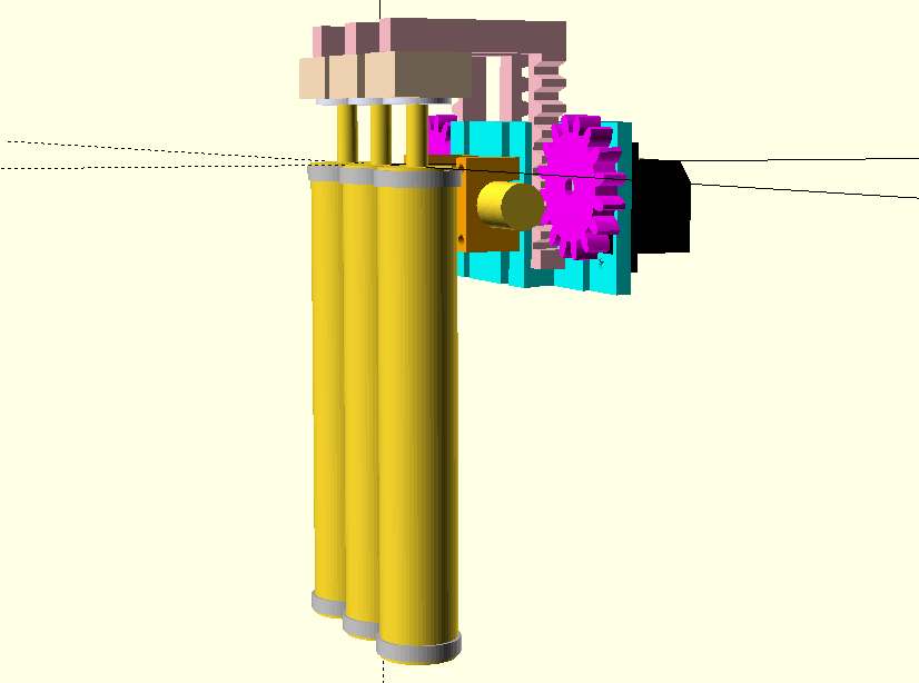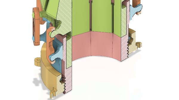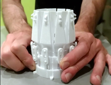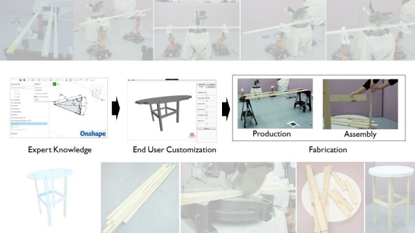
Whether it’s a 3D printed robot chassis or a stained glass window, looking at a completed object and trying to understand how it was designed and put together can be intimidating. But upon closer examination, you can often identify the repeating shapes and substructures that were combined to create the final piece. Soon you might find that the design that seemed incredibly intricate when taken as a whole is actually an amalgamation of simple geometric elements.
This skill, the ability to see an object for its principle components, is just as important for designing new objects as it is for understanding existing ones. As James McBennett explains in his HackadayU course Designing with Complex Geometry, if you want to master computer-aided design (CAD) and start creating your own intricate designs, you’d do well to start with a toolbox of relatively straightforward geometric primitives that you can quickly modify and reuse. With time, your bag of tricks will be overflowing with parametric structures that can be reshaped on the fly to fit into whatever you’re currently working on.
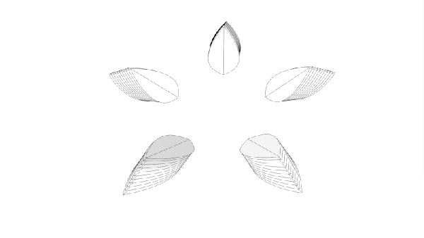
His tool of choice is Grasshopper, a visual programming language that’s part of Rhino. Designs are created using an interface reminiscent of Node-RED or even GNU Radio, with each interconnected block representing a primitive shape or function that can be configured through static variables, interactive sliders, conditional operations, and even mathematical expressions. By linking these modules together complex structures can be generated and manipulated programmatically, greatly reducing the time and effort required compared to a manual approach.

As with many powerful tools, there’s certainly a learning curve for Grasshopper. But over the course of this five part series, James does a great job of breaking things down into easily digestible pieces that build onto each other. By the final class you’ll be dealing with physics and pushing your designs into the third dimension, producing elaborate designs with almost biological qualities.
Of course, Rhino isn’t for everyone. The $995 program is closed source and officially only runs on Windows and Mac OS. But the modular design concepts that James introduces, as well as the technique of looking at large complex objects as a collection of substructures, can be applied to other parametric CAD packages such as FreeCAD and OpenSCAD.
Designing with Complex Geometry is just one of the incredible courses offered through HackadayU, our pay-as-you-wish grad school for hardware hackers. From drones to quantum computing, the current list of courses has something for everyone.
Continue reading “New Video Series: Designing With Complex Geometry”