Take This Cylindrical Coupler Design For A Spin

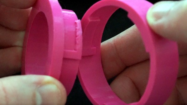
We’re not exactly sure what kind of shenanigans [Conrad Brindle] gets himself into, but apparently it often requires cylindrical couplings to attach 3D printed parts to each other. He found himself designing and redesigning this type of connector so often that he decided to just make a parametric version of it that could be scaled to whatever dimensions are necessary for that particular application.

In the video after the break, [Concrad] explains the concept behind the coupler and how he designed it. Put simply, the tabs inside of the coupler are designed to grab onto each other once the coupler is spun. When he demonstrates the action, you can see that both sides of the coupler are pulled together tightly with a satisfying little snap, but then can be easily removed just by rotating them back in the opposite direction.

The nature of desktop 3D printing means that the female side of the connection requires support when printing, and depending on your printer, that might mean a relatively rough mating surface. [Conrad] notes that you’ll need to experiment a bit to find how small your particular machine can print out the design before things get too gummed up.

We can see how this would be useful for some applications, but if you need a printed joint that can handle a decent amount of torque before giving up the ghost, you might want to look into (mis)using one half of a spider coupling.

Continue reading “Take This Cylindrical Coupler Design For A Spin”

An OpenSCAD Mini-ITX Computer Case

We’re no strangers to 3D printed enclosures here at Hackaday. From the plethora of printed Raspberry Pi cases out there to custom enclosures for electronic projects, small plastic boxes turn out to be an excellent application for desktop 3D printing. But as printers get bigger and filament gets cheaper, those little boxes don’t always need to be so little. We aren’t talking about running off boxes for your sneaker collection either, if you’ve got the time and the print volume, you could whip up an enclosure for your PC.

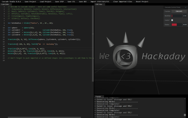
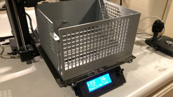
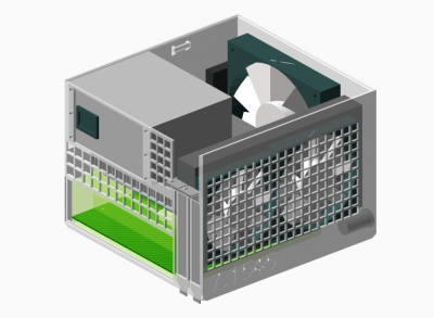
[Nirav Patel] writes in to share his impressive 3D printed Mini-ITX computer case project, which would be a neat enough trick in its own right, but he took the concept one step farther and made it a parametric design in OpenSCAD. This allows the user to input their particular hardware configuration and receive STL files for a bespoke case. The list of supported hardware isn’t that long yet, but with the OpenSCAD code up on GitHub and released under the BSD license, hopefully the community can improve on that as time goes on.

To keep things simple (and strong), [Nirav] implemented what he refers to as a “bucket” design. The majority of the case is a single print, which does take a long time (just shy of 40 hours on his Prusa i3 MK3), but nearly eliminates any post-printing assembly. Only the optional feet and the lid need to be printed separately. Threaded inserts are used throughout the design for mounting hardware, so you don’t run the risk of blowing out the printed holes during hardware changes or upgrades.

A particularly neat feature, and a testament to the power of OpenSCAD, is the fact that the case’s internal volume is calculated and embossed into the side of the design. Does this have any practical purpose? Not exactly, but [Nirav] thought it would be appealing to the Mini-ITX case modding community which apparently measures their accomplishments in liters of volume.

We’ve seen a 3D printed computer case before, but it used acrylic sheets and couldn’t be made without a large format printer. There’s something to be said for a project that can be completed on the hacker community’s favorite printer.

Robotic Wood Shop Has Ambitions To Challenge IKEA

Many people got their start with 3D printing by downloading designs from Thingiverse, and some of these designs could be modified in the browser using the Thingiverse Customizer. The mechanism behind this powerful feature is OpenSCAD’s parametric design capability, which offers great flexibility but is still limited by 3D printer size. In the interest of going bigger, a team at MIT built a system to adopt parametric design idea to woodworking.

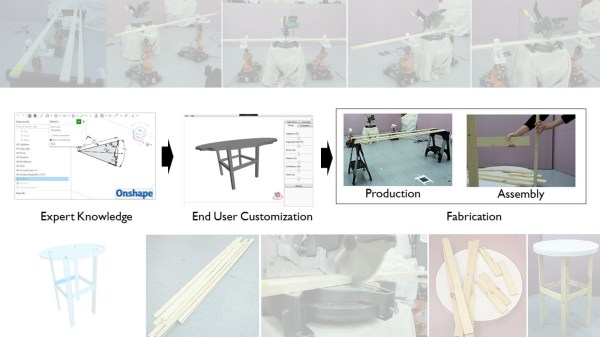
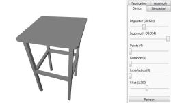
The “AutoSaw” has software and hardware components. The software side is built on web-based CAD software Onshape. First the expert user builds a flexible design with parameters that could be customized, followed by one or more end users who specify their own custom configuration.

Once the configuration is approved, the robots go to work. AutoSaw has two robotic woodworking systems: The simpler one is a Roomba mounted jigsaw to cut patterns out of flat sheets. The more complex system involves two robot arms on wheels (Kuka youBot) working with a chop saw to cut wood beams to length. These wood pieces are then assembled by the end-user using dowel pegs.

AutoSaw is a fun proof of concept and a glimpse at a potential future: One where a robotic wood shop is part of your local home improvement store’s lumber department. Ready to cut/drill/route pieces for you to take home and assemble.

Continue reading “Robotic Wood Shop Has Ambitions To Challenge IKEA”

Autodesk Introduces Parametric Part Generation

The hardest part of any PCB design is adding parts and components. You shouldn’t use random part libraries, and creating your own part libraries is just a pain. Why have we endured this pain for so long, especially considering that most components follow a standard? Add in the fact that 3D modeling and rendering a board in a mechanical CAD tool is now a thing, making creating your own part libraries even more involved.

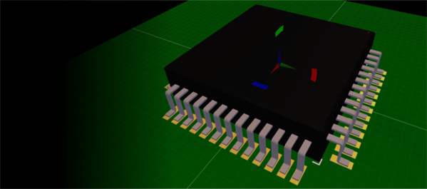
To solve this problem, Autodesk has introduced library.io, a tool to parametrically generate component footprints for Eagle and 3D models for Fusion360. Given that most parts follow a standard — QFP, TO-, DFN, or SOT23 — this is now the easiest way to create a new part in Eagle with its own 3D model that allows you to bring it into mechanical CAD tools.

An overview parametric parts generation is written up on the Autodesk forums, and covers what is possible with this new tool. There are actually two distinct versions, one is a web-based app that allows you to create packages and footprints parametrically in your browser and export them as a library. The other version of the tool is integrated with Eagle and allows you to create a new component parametrically from within Eagle.

This is a far cry from the standard method of creating new footprints. Instead of toiling over a datasheet and dropping correctly sized pads onto a grid, creating a new parametric footprint is as easy as copying a few numbers. In addition to the new parametric design feature, there’s a new tool in Eagle that does away with placing and naming pins for symbols. Now you can simply cut and paste a list of pins from the datasheet.

It should be noted that everything created with the library.io tool can be downloaded and used offline. Combine that with the recent news that KiCad can now ingest Eagle board and schematic files, and you have a way to create parametric footprints in everyone’s favorite Open Source PCB tool as well.

Printed It: Custom Enclosure Generator

You’ve written your firmware code, etched your own PCB, and now it’s time to put that awesome new project of yours into an enclosure. Unfortunately, all you have is a generic Radio Shack project box that you picked up when they were clearing out their inventory. If you put your project in that, it’ll have all the style and grace of a kid wearing hand-me-down clothes. Your project deserves a tailor-made enclosure, but the prices and lead time on custom plastic enclosures are prohibitive for one-off projects.

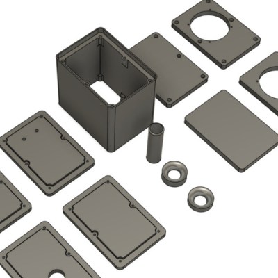
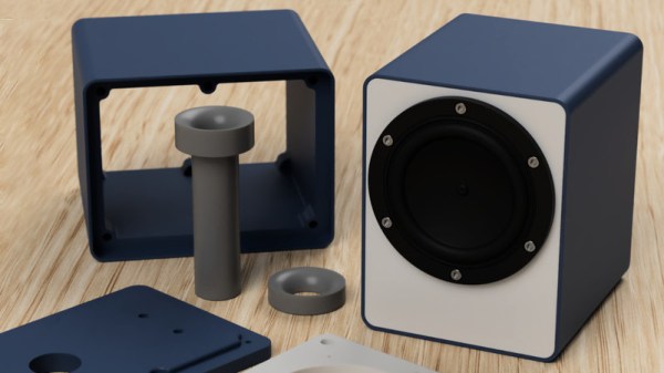
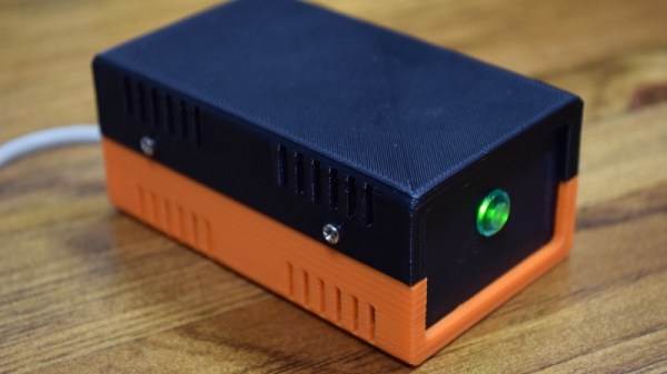
In Ye Olde Olden Days, the next step might have been to start bending some sheet metal. But it’s the 21st century, and we’ve got mechanization on our side. The “Ultimate Box Maker” by [Heartman] is a fully parametric OpenSCAD design which allows you to generate professional looking enclosures by simply providing your desired dimensions and selecting from a few optional features. In a couple of hours, you’ll have a custom one-of-a-kind enclosure for your project for a few cents worth of filament.

That’s the idea, at least. For this edition of “Printed It”, I’ll be taking a look at the “Ultimate Box Maker” by generating and printing a basic enclosure. As somebody whose Radio Shack was out of enclosures by the time I got there and who doesn’t want to slice his hand open folding sheet metal, I’m very interested in seeing how well this design works.

Continue reading “Printed It: Custom Enclosure Generator”

Big Slew Bearings Can Be 3D Printed

Consider the humble ball bearing. Ubiquitous, useful, and presently annoying teachers the world over in the form of fidget spinners. One thing ball bearings aren’t is easily 3D printed. It’s hard to print a good sphere, but that doesn’t mean you can’t print your own slew bearings for fun and profit.

As [Christoph Laimer] explains, slew bearings consist of a series of cylindrical rollers alternately arranged at 90° angles around an inner and outer race, and are therefore more approachable to 3D printing. Slew bearings often find application in large, slowly rotating applications like crane platforms or the bearings between a wind turbine nacelle and tower. In the video below, [Christoph] walks us through his parametric design in Fusion 360; for those of us not well-versed in the app, it looks a little like magic. Thankfully he has provided both the CAD files and a selection of STLs for different size bearings.

[Christoph] is no stranger to complex 3D-printable designs, like his recent brushless DC motor or an older clock build. The clock is cool, but the bearings and motors really get us — we’ll need such designs to get to self-replicating machines.

Continue reading “Big Slew Bearings Can Be 3D Printed”

Two-Piece Boxes Thanks To Laser-Cut Flex Hinges

It sounds like a challenge from a [Martin Gardner] math puzzle from the Scientific American of days gone by: is it possible to build a three-dimensional wooden box with only two surfaces? It turns out it is, if you bend the rules and bend the wood to make living hinge boxes with a laser cutter.

[Martin Raynsford] clearly wasn’t setting out to probe the limits of topology with these boxes, but they’re a pretty neat trick nonetheless. The key to these boxes is the narrow to non-existent kerf left by a laser cutter that makes interference fits with wood a reality. [Martin]’s design leverages the slot and tab connection we’re used to seeing in laser-cut boxes, but adds a living flex-hinge to curve each piece of plywood into a U-shape. The two pieces are then nested together like those old aluminum hobby enclosures from Radio Shack. His GitHub has OpenSCAD scripts to parametrically create two different styles of two-piece boxes so you can scale it up or (somewhat) down according to your needs. There’s also a more traditional three-piece box, and any of them might be a great choice for a control panel or small Arduino enclosure. And as a bonus, the flex-hinge provides ventilation.

Need slots and tabs for boxes but you’re more familiar with FreeCAD? These parametric scripts will get you started, and we’ll bet you can port the flex-hinge bit easily, too.