DeepPCB Routes Your KiCAD PCBs

Computers can write poetry, even if they can’t necessarily write good poetry. The same can be said of routing PC boards. Computers can do it, but can they do it well? Of course, there are multiple tools each with pluses and minuses. However, a slick web page recently announced deeppcb.ai — a cloud-based AI router — and although details are sparse, there are a few interesting things about the product.

First, it supports KiCAD. You provide a DSN file, and within 24 hours you get a routed SES file. Maybe. You get three or four free boards –apparently each week — after which there is some undisclosed fee. Should you just want to try it out, create an account (which is quick and free — just verify your e-mail and create a password). Then in the “Your Boards” section there are a few examples already worked out.

Continue reading “DeepPCB Routes Your KiCAD PCBs”

Add A Bit Of PCB Badge Glamour To Your Boring ID Badge

When we talk about badges and printed circuit boards, it is usually in the context of the infinite creativity of the Badgelife scene, our community’s own art form of electronic conference badges. It’s easy to forget when homing in on those badges that there are other types of badge, and thus [Saimon]’s PCB badge holder is an entertaining deviation from our norm. His workplace requires employees to carry their credit-card-sized ID pass with them at all times, but the plastic holder that came with his had broken. So he did what any self-respecting engineer would do, and designed his own holder using PCBs.

It’s a three-way sandwich with identical front and back PCBs featuring a nice design, but the clever bit is the middle PCB. It is U-shaped to slide the card in from the side, but to retain the card it has a couple of springy milled PCB arms each with a small retaining tooth on the end. This is an ingenious solution, with just enough give to bend, but not so much as to break.

The three boards are glued together, it seems his original aim was to reflow solder them but this was not successful. The result is an attractive and functional badge holder, which if Hackaday required us to have a corporate ID you can be sure we’d be eyeing up for ourselves.

Beam Me Up To The PCB Space Ship

This project would fit in perfectly with #BadgeLife if someone could figure out a way to hang it from their neck. Inspired by Star Trek’s Starship Enterprise, [bobricius] decided to design and assemble a miniature space ship PCB model, complete with 40 blinking LEDs controlled by an ATtiny85.

While the design uses 0603, 0802, 3014, 4014, and 0805 LEDs, some substitutions can be made since the smallest LEDs can be difficult to solder. The light effects include a green laser, plasma coils, a deflector with scrolling blue LEDs, and the main plate and bridge for the space ship.

The LEDs are controlled by charlieplexing, a technique for driving LED arrays with relatively few I/O pins, different from traditional multiplexing. Charlieplexing allows n pins to drive n2−n LEDs, while traditional multiplexing allows n pins to drive (n/2)2 LEDs. (Here is the best explanation of Charlieplexing we’ve ever seen.)

Especially with the compiled firmware running on the MCU, the PCB model makes for an impressive display.

The only catch? Your Starship Enterprise can’t actually fly.

Continue reading “Beam Me Up To The PCB Space Ship”

Nixie Clock Failure Analysis, [Dalibor Farný] Style

We’ve become sadly accustomed to consumer devices that seem to give up the ghost right after the warranty period expires. And even when we get “lucky” and the device fails while it’s still covered, chances are that there will be no attempt to repair it; the unit will be replaced with a new one, and the failed one will get pitched in the e-waste bin.

Not every manufacturer takes this approach, however. When premium quality is the keystone of your brand, you need to take field failures seriously. [Dalibor Farný], maker of high-end Nixie tubes and the sleek, sophisticated clocks they plug into, realizes this, and a new video goes into depth about the process he uses to diagnose issues and prevent them in the future.

One clock with a digit stuck off was traced to via failure by barrel fatigue, or the board material cracking inside the via hole and breaking the plated-through copper. This prompted a board redesign to increase the diameter of all the vias, eliminating that failure mode. Another clock had a digit stuck on, which ended up being a short to ground caused by pin misalignment; when the tube was plugged in, the pins slipped and scraped some solder off the socket and onto the ground plane of the board. That resulted in another redesign that not only fixed the problem by eliminating the ground plane on the upper side of the board, but also improved the aesthetics of the board dramatically.

As with all things [Dalibor], the video is a feast for the eyes with the warm orange glow in the polished glass and chrome tubes contrasting with the bead-blasted aluminum chassis. If you haven’t watched the “making of” video yet, you’ve got to check that out too.

Continue reading “Nixie Clock Failure Analysis, [Dalibor Farný] Style”

Dealing With Missing Pin Allocations

Blindsided by missing pin allocations? Perhaps you’re working on a piece of hardware and you notice that the documentation is entirely wrong. How can you get your device to work?

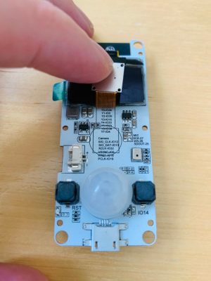
[Dani Eichhorn]’s troubles began when running an IoT workshop using a camera module. Prior to the work, no one had through to check if all of the camera modules ordered for the participants were the same. As it turns out, the TTGO T-CAM module had a number of revisions, with some even receiving a temperature/pressure sensor fixed on top of the normal board.

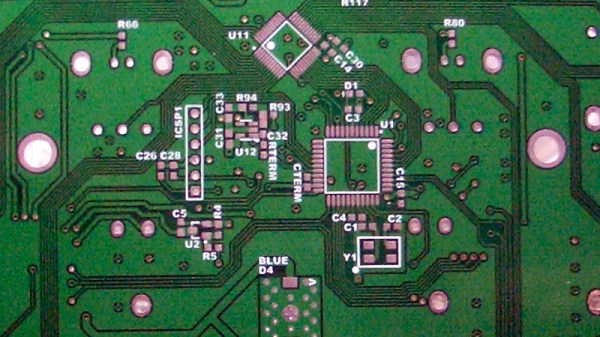
While the boards may have looked the same, their pin allocations were completely different.Changing the pin numbers wouldn’t have been difficult if they were simply numbered differently, but because the configurations were different, errors started to abound: Could not initialize the camera

As it turns out, even the LillyGo engineers – the manufacturers of the board – may have gotten a bit lost while working on the pin allocations, as [Eichhorn] was able to find some of the pins printed right onto the PCB, hidden behind the camera component.

To find information not printed on the board, a little more digging was required. To find the addresses of the devices connected to the I2C bus, running a program to find peripherals listening on the bus did the trick. This was able to print out the addresses of the SSD1306 OLED display driver and the microphone for the board at hand.

To find the pins of peripherals not printed on the PCB or hidden on the silkscreen, a GPIO scanner did the trick. This in particular worked for finding the PIR (passive infrared) motion sensor.

We picked up a few tips and tricks from this endeavor, but also learned that reverse-engineering anything is hard, and that there isn’t any one method for finding pin allocations when the documentation’s missing.

This Home-Etched ARM Dev Board Is A Work Of Art

One of the step changes in electronic construction at our level over the last ten or fifteen years has been the availability of cheap high-quality printed circuit boards. What used to cost hundreds of dollars is now essentially an impulse buy, allowing the most intricate of devices to be easily worked with. Many of us have put away our etching baths for good, often with a sigh of relief.

We’re pleased that [Riyas] hasn’t though, because they’ve etched an STM32 dev board that if we didn’t know otherwise we’d swear had been produced professionally. It sports a 176-pin variant of an STM32F4 on a single-sided board, seemingly without the annoying extra copper or lack-of-copper that we remember from home etching. We applaud the etching skill that went into it, and we’ll ignore the one or two boards that didn’t go entirely to plan. A coat of green solder mask and some tinning, and it looks for all the world as though it might have emerged from a commercial plant. All the board files are available to download along with firmware samples should you wish to try making one yourself, though we won’t blame you for ordering it from a board house instead.

It’s always nice to see that single board computers are not the sole preserve of manufacturers. If the RC2014 Micro doesn’t isn’t quite your style, there’s always the Blueberry Pi which features a considerably higher penguin quotient.

The Benefits And Pitfalls Of Using PCBs As An Enclosure

[Mastro Gippo] found himself in a pickle recently, with the development of an enclosure for the Prism electric vehicle charger. The body had been sorted out, but the front cover needed work. It had to be visually appealing, and ideally should provide the user feedback on the charging process. After some thought, [Mastro] decided to explore the possibilities of using a PCB as a part of a commerical product enclosure.

For a variety of reasons, using a specially designed PCB was an attractive solution for the team’s enclosure. Wanting something cost effective, easily customizable, and something that would help with emissions compliance, a PCB seemed like a great idea. With this in mind, [Mastro] prepared a series of prototypes. These feature see-through sections for LEDs to shine through, as well as a capacitive button and gold-plated logo. The fact that the front cover is a PCB makes the integration of the electronic components a cinch.

Before heading into full production, [Mastro] began to question why this technique isn’t used more often. Deciding to research further, [Bunnie Huang] was tapped to provide some advice on the concept. Noting that there can be issues with lead content, as well as the fact that PCBs aren’t often produced with proper regard to aesthetics, there were some pitfalls to the idea. Additionally, ESD testing can be difficult, while the in-built capacitive button would face issues in wet conditions.

None of these are showstoppers however, and [Mastro] has persevered, combining the front cover PCB with an adhesive plastic sheet for added protection. We fully expect that if more manufacturers explore this route, it may be a more viable technique in future. It’s also a great example of knowing when to ask others for help – it’s not the first time we’ve learned from [Bunnie’s] broad experience!