Temperature Logger

Logging Engine Temperature For RC Models

[Rui] enjoys his remote-controlled helicopter hobby and he was looking for a way to better track the temperature of the helicopter’s engine. According to [Rui], engine temperature can affect the performance of the craft, as well as the longevity and durability of the engine. He ended up building his own temperature logger from scratch.

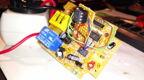
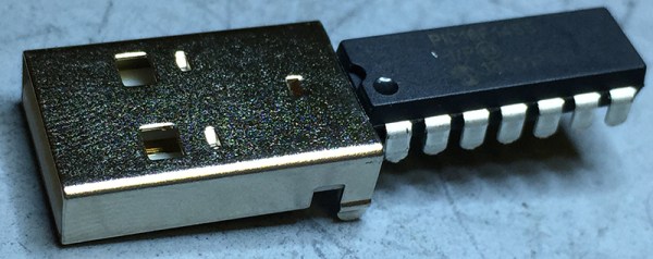
The data logger runs from a PIC 16F88 microcontroller mounted to a circuit board. The PIC reads temperature data from a LM35 temperature sensor. This device can detect temperatures up to 140 degrees Celsius. The temperature sensor is mounted to the engine using Arctic Alumina Silver paste. The paste acts as a glue, holding the sensor in place. The circuit also contains a Microchip 24LC512 EEPROM separated into four blocks. This allows [Rui] to easily make four separate data recordings. His data logger can record up to 15 minutes of data per memory block at two samples per second.

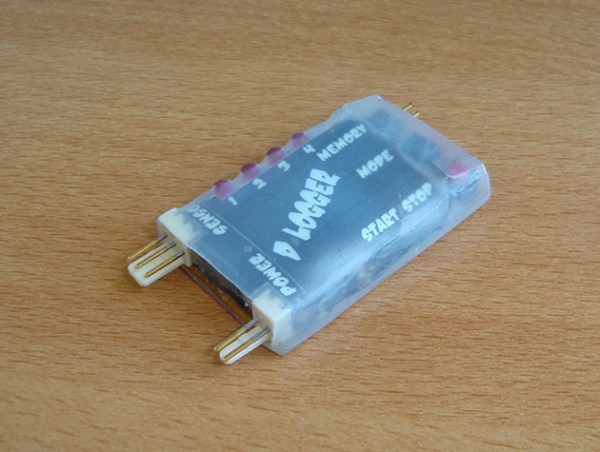
Three buttons on the circuit allow for control over the memory. One button selects which of the four memory banks are being accessed. A second button changes modes between reading, writing, and erasing. The third button actually starts or stops the reading or writing action. The board contains an RS232 port to read the data onto a computer. The circuit is powered via two AA batteries. Combined, these batteries don’t put out the full 5V required for the circuit. [Rui] included a DC-DC converter in order to boost the voltage up high enough.

Game And Watch

Give In To Nostalgia With A Retro Game And Watch

One of the earliest Nintendo products to gain popularity was the Game and Watch product line. Produced by Nintendo between 1980 and 1991, they are a source of nostalgia for many an 80s or 90s kid. These were those electronic handheld games that had pre-drawn monochrome images that would light up to make very basic animations. [Andrew] loved his old “Vermin” game as a kid, but eventually he sold it off. Wanting to re-live those childhood memories, he decided to build his own Game and Watch emulator.

The heart of [Andrew’s] build is a PIC18F4550 USB demo board he found on eBay. The board allows you to upload HEX files directly via USB using some simple front end software. [Andrew] wrote the code for his game in C using MPLAB. His device uses a Nokia 5110 LCD screen and is powered from a small lithium ion battery.

For the housing, [Andrew] started from another old handheld game that was about the right size. He gutted all of the old parts and stuck the new ones in their place. He also gave the housing a sort of brushed metal look using spray paint. The end result is a pretty good approximation of the original thing as evidenced by the video below. Continue reading “Give In To Nostalgia With A Retro Game And Watch”

Hacking A Wireless AC Power Outlet

It’s always nice to see hackers pick up stuff headed for the landfill and put it back in action with a quick repair and upgrade. [Septillion] found a wireless remote controlled AC outlet in the junk bin and decided to do just that. A nice spin-off of such hacks is that we end up learning a lot about how things work.

His initial tests showed that the AC outlet and its remote could be revived, so he set about exploring its guts. These remote AC outlets consist of an encoder chip on the remote and a corresponding decoder chip on the outlet, working at 433MHz.  Since the various brands in use have a slightly different logic, it needed some rework to make them compatible. The transmit remote was a quick fix – changing the DIP switch selected address bits from being pulled low to high and swapping the On and Off buttons to make it compatible with the other outlets.

Working on the AC outlet requires far more care and safety. The 230V AC is dropped down using a series capacitor, so the circuit is “hot” to touch. Working on it when it is powered up requires extreme caution. A quick fix would have been to make the changes to the address bits and the On/Off buttons to reflect the changes already made in the remote transmitter. Instead, he breadboarded a small circuit around the PIC12F629 microcontroller to take care of the data and address control. Besides, he wanted to be able to manually switch the AC outlet. The relay control from the decoder was routed via the microcontroller. This allowed either the decoder or the local manual switch from controlling the relay. Adding the PIC also allowed him to program in a few additional modes of operation, including one which doubled the number of outlets he could switch with one remote.

Hackaday Prize Entry: A Two Component Temperature Sensor

Here’s a design challenge for you: make a temperature sensor for any computer. If you’re an exceptionally clever smart ass, you’ll probably write some code to report the CPU temps. Others who take the exercise seriously will probably build something with a 1-wire temp sensor, a microcontroller, and all the hardware required to do that.

[Michael] had a better idea. He did it with just two components. One of those components is a USB connector.

The only reason is project could be created is a rather new part from Microchip, the PIC16F1455. This microcontroller doesn’t require a crystal, can do USB without any additional parts, and has an integrated temperature sensor. [Michael] whipped up a project to set up a USB CDC serial device, read the temperature with the ADC (thanks to a very helpful app note), and sends the temperature to a computer once a second.

Despite being built out of only two components, this could actually be a useful device. The PIC is a USB serial device, and this can be used with any computer made in the past 15 or so years. It would hardly take any code at all to read the temperature with another program, and it’s a very inexpensive build. We have to give style points for soldering a microcontroller directly to a USB connector, too.


The 2015 Hackaday Prize is sponsored by:

DIY ESP8266 Development Board

Those small, super-cheap, ESP8266 modules are being installed everywhere, creating all sorts of frivolous internet connected thingamajigs. But consider this period as a training ground of sorts, as hackers smarten their chops on figuring out how to get the best out of this IoT gravy train. Right now, getting the ESP8266 to work requires a fair amount of work and to make things easier, [Abdulgafur] built a ESP8266 development board.

The dev board lets the user connect the ESP8266 to a PIC micro controller as well as to a host PC. In addition, it hosts several peripherals such as a 2×16 LCD display, 4 push buttons, couple of indicator LEDs and some GPIO’s broken out to a header. PC communication is via a FT232RL USB-UART converter over a Mini-USB connector. There’s also a few bi-directional level converters to translate between 5V and 3.3V and pull-up resistors for the ESP8266.

As of now, the dev board only supports the ESP8266-01 module. A nice upgrade would be to add support for other ESP8266 modules too. Maybe a separate, 3d printed, pogo pinned, test fixture for the other modules. If you plan to build you own version, [Abdulgafur] has the schematic, PCB and BoM available for download, although we couldn’t spot the PIC code, so you might have to ask for that. And it would be a good idea to remove the GND copper pour from under the ESP8266 footprint.

Binary Wristwatch

Open Source Binary Wristwatch Is Professional Quality

If you want to proclaim to the world that you’re a geek, one good way to go about it is to wear a wristwatch that displays the time in binary. [Jordan] designs embedded systems, and he figured that by building this watch he could not only build up his geek cred but also learn a thing or two about working with PIC microcontrollers for low power applications. It seems he was able to accomplish both of these goals.

The wristwatch runs off of a PIC18F24J11 microcontroller. This chip seemed ideal because it included a built in real-time clock and calendar source. It also included enough pins to drive the LEDs without the need of a shift register. The icing on the cake was a deep sleep mode that would decrease the overall power consumption.

The watch contains three sets of LEDs to display the information. Two green LEDs get toggled back and forth to indicate to the user whether the time or date is being displayed. When the time is being displayed, the green LED toggles on or off each second. The top row of red LEDs displays either the current hour or month. The bottom row of blue LEDs displays the minutes or the day of the month. The PCB silk screen has labels that help the user identify what each LED is for.

The unit is controlled via two push buttons. The three primary modes are time, date, and seconds. “Seconds” mode changes the bottom row of LEDs so they update to show how many seconds have passed in the current minute. [Jordan] went so far as to include a sort of animation in between modes. Whenever the mode is changed, the LED values shift in from the left. Small things like that really take this project a step further than most.

The board includes a header to make it easy to reprogram the PIC. [Jordan] seized an opportunity to make extra use out of this header. By placing the header at the top of the board, and an extra header at the bottom, he was able to use a ribbon cable as the watch band. The cable is not used in normal operation, but it adds that extra bit of geekiness to an already geeky project.

[Jordan] got such a big response from the Internet community about this project that he started selling them online. The only problem is he sold out immediately. Luckily for us, he released all of the source code and schematics on GitHub so we can make our own.

Revive The Demoscene With A LayerOne Demoscene Board

Demos, the demoscene, and all the other offshoots of computer arts had their beginning as intros for cracked Apple II, Speccy, and Commodore 64 games. Give it a few years, and these simple splash screens would evolve into a technological audio-visual experience. This is the birth of the demoscene, where groups of programmers would compete to create the best demonstration of computer graphics and audio.

For one reason or another, this demoscene was mostly confined to Europe; even today, 30 years after the Commodore 64, the North American demoscene is just a fraction of the size of the European scene. A very cool guy named [Arko] would like to change that, and to that end he built the LayerOne Demoscene Board.

If there is a problem with the modern demo scene, it’s that the hardware that’s usually used – C64s, Ataris, Spectrums, and Amigas – are old, somewhat rare, and dying. There’s also the fact that artists have been working on these old machines for decades now, and every single ounce of processing power and software trickery has been squeezed out of these CPUs. [Arko]’s board is a ground-up redesign of what a board that plays demos should be. There’s only one chip on the board – a PIC24F with three graphics acceleration units, color lookup tables, and the ability to output 16-bit VGA video up to 640×480 with 8-bit audio.

The first official competition with the LayerOne Demoscene Board will be at the 2015 LayerOne conference in Monrovia, CA on May 23. There are a few categories, including 4k and 64k JavaScript, Raspberry Pi, the LayerOne board, and a ‘Wild’ category. If you want to take a processor out of a toaster and make a demo, this is the category you’ll be entering. Of course Hackaday will be there, and we’ll be recording all the demos.

Below are a few examples of what the LayerOne Demoscene board can do, and you can also see a talk [Arko] gave at the Hackaday 10th anniversary party here. You can buy the Layerone Demoscene Board on the Hackaday Store

Continue reading “Revive The Demoscene With A LayerOne Demoscene Board”