PCB Tesla Coil Is Perfect Desk Toy

A Tesla coil easily makes it to the top spot on our list of “Mad Scientist” equipment we want for the lab, second only to maybe a Jacob’s Ladder. Even then, it’s kind of unfair advantage because you know people only want a Jacob’s Ladder for that awesome sound it makes. Sound effects not withstanding, it’s Tesla coil all the way, no question.

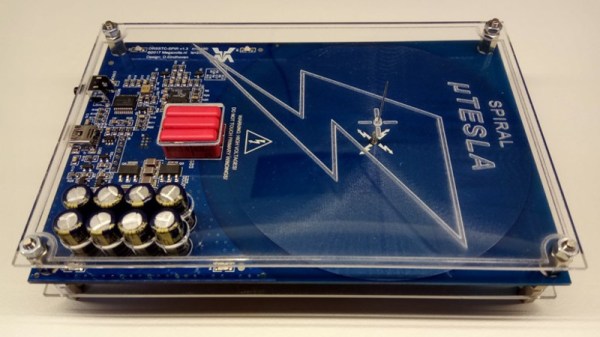
Unfortunately, winding your own Tesla coil is kind of a hassle. Even on relatively small builds, you’ll generally need to setup some kind of winding jig just to do the secondary coil, which can be a project in itself. So when [Daniel Eindhoven] sent his no-wind Tesla coil into the tip line, it immediately got our attention.

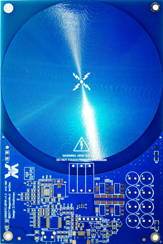
The genius in his design is that the coils are actually etched into the PCB, completely taking the human effort out of the equation. Made up of 6 mil traces with 6 mil separation, the PCB coil manages to pack a 25 meter long, 160 turn coil into an incredibly compact package. As you might expect, such a tiny Tesla coil isn’t exactly going to be a powerhouse, and in fact [Daniel] has managed to get the entirely thing running on the 500 mA output of your standard USB 2.0 port.

In such a low-power setup, [Daniel] was also able to replace the traditional spark gap pulse generator with a PIC18F14K50 microcontroller, further simplifying the design. An advantage of using a microcontroller for the pulse generator is that it’s very easy to adjust the coil’s operating frequency, allowing for neat tricks like making the coil “sing” by bringing its frequency into the audible range.

For those looking to build their own version, [Daniel] has put the PCB schematic and firmware available for download on his site. He also mentions that, in collaboration with Elektor magazine, he will be producing a kit in the near future. Definitely something we’ll be keeping an eye out for.

Incidentally, this isn’t the first time [Daniel] has demonstrated his mastery of high voltage. He scared impressed us all the way back in 2010 with his 11,344 Joule capacitor bank, perfect for that laptop-destroying rail gun you’ve been meaning to build.

Continue reading “PCB Tesla Coil Is Perfect Desk Toy”

Microchip ICD4 REview

[Mike] is an avid PIC developer and replaced his ICD3 debugger for an ICD4. He made a video with his impressions and you can see it below. [Mike] found the heavy aluminum case with a sexy LED attractive, but wondered why he was paying for that in a development tool. He was also unhappy that they replaced the ICD3 cable connections with new connectors. Finally, he wished for the pin out to be printed on the case.

On the other hand, the ICD4 will also do JTAG and handle the Atmel parts (which Microchip acquired). [Mike] opens the box and shows the inside of the device before actually using it for the intended task.

Continue reading “Microchip ICD4 REview”

Garage Distance Sensor Kicks Tennis Ball To Curb

Those with small garages might be familiar with the method of hanging a tennis ball from a ceiling to make sure they don’t hit the back wall with their car. If the car isn’t in the garage, though, the tennis ball dangling from a string tends to get in the way. To alleviate this problem, [asaucet] created a distance sensor that can tell him when his car is the perfect distance from the garage wall.

At the heart of the distance sensor is an HC-SR04 ultrasonic rangefinder and a PIC16F88 microcontroller. [asaucet] uses a set of four LEDs to alert the driver how close they are to the garage wall. [asaucet] also goes into great detail about how to use an LCD with this microcontroller for setting up the project, and the amount of detail should be enough to get anyone started on a similar project.

While this isn’t a new idea, the details that [asaucet] goes into in setting up the microcontroller, using the distance sensor, and using an LCD are definitely worth looking into. Even without this exact application in mind, you’re sure to find some helpful information on the project page.

Continue reading “Garage Distance Sensor Kicks Tennis Ball To Curb”

Digitool Helps Debugging

Logic analyzers used to be large boxes full of high-speed logic and a display monitor. Today, they are more likely to be a small box with a USB port that feeds data to a PC application. [Juan Antonio Rubia Mena] wanted something more self-contained, so he built Digitool. Built around a PIC18F2525, the device can measure frequency up to 10 MHz and inject square waves up to 1 MHz into the circuit under test. Oh yeah. It also has a simple four-channel logic analyzer that displays on a tiny LCD.

The 500,000 sample per second rate and the 1024 sample buffer isn’t going to put any logic analyzer vendors out of business, but it is still enough to help you figure out why that SPI or I2C logic is messed up. It looks like a fun project that could have some usefulness.

Continue reading “Digitool Helps Debugging”

Friday Hack Chat: 8-Bit Micros With Microchip

A few years ago, Microchip acquired Atmel for $3.56 Billion. There are plenty of manufacturers of 8-bit microcontrollers, but everyone makes 8051s, and the MSP430 isn’t as popular as it should be. Microchip’s acquisition of Atmel created what is probably the largest manufacturer of 8-bit micros, with a portfolio ranging from ATtinys smaller than a grain of rice to gigantic PICs.

This Friday, we’re hosting a Hack Chat with the Technical Marketing Engineer of 8-bitters at Microchip. If you love AVR, this is the guy to talk to. If you’re still rocking the vintage 1993 PICkit, this is the guy to talk to.

On the docket for this Hack Chat are some new PICs and some very interesting peripherals coming down the line. ADCC — A2D with computation — is on the table, along with configurable logic cells. This Hack Chat is also going to go over Microchip design tools like MP Lab Xpress.

Of course, these Hack Chats are a question and answer session for the community. We’re encouraging everyone to ask a few questions about what Microchip is doing. We’ve opened up a discussion guide for this Hack Chat. If you have a question, just add it to the list.

If you can’t make the Hack Chat, don’t worry. We’re going to have a transcript of the entire chat. That should be available here shortly after the chat concludes.

Here’s How To Take Part:

join-hack-chatOur Hack Chats are live community events on the Hackaday.io Hack Chat group messaging. This hack chat will take place at noon Pacific time on Friday, June 9th. Here’s a fancy time and date converter if you need timezone help.

Log into Hackaday.io, visit that page, and look for the ‘Join this Project’ Button. Once you’re part of the project, the button will change to ‘Team Messaging’, which takes you directly to the Hack Chat.

You don’t have to wait until Friday; join whenever you want and you can see what the community is talking about

Making An Inexpensive DRO

[Andrew] wanted a digital readout (DRO) for his mini lathe and mini mill, but found that buying even one DRO cost as much as either of his machines. The solution? You guessed it, he built his own for cheap, using inexpensive digital calipers purchased off eBay.

The DRO he created features a touch screen with a menu system running on an LPCXpresso, while smaller OLED screens serve as labels for the 7-segment displays to the right. The DRO switches back and forth between the lathe and mill, and while the software isn’t done, [Andrew] hopes to be able to transfer measurements from one machine to the other.

In a very sweet touch, [Andrew] hacked cheap digital calipers to provide measurements for each axis, where they provide a resolution of 0.01mm. There are six daughter boards, one for each caliper, and each has a PIC that converts from serial to I2C, freeing the main firmware from dealing with six separate data streams.

The DRO doesn’t have a case, [Andrew] has it positioned out of chip-range from either machine.

A previous DRO we featured in 2012 used an Android tablet as its display.

Microchip Launches New Family Of PICs

Over the last few years, we’ve seen projects and products slowly move from 8-bit microcontrollers to more powerful ARM microcontrollers. The reason for this is simple — if you want to do more stuff, like an Internet-connected toaster, you need more bits, more Flash, and more processing power. This doesn’t mean 8-bit microcontrollers are dead, though. Eight bit micros are still going strong, and this week Microchip announced their latest family of 8-bit microcontrollers.

The PIC16F15386 family of microcontrollers is Microchip’s latest addition to their portfolio of 8-bit chips. This family of microcontrollers is Microchip’s ‘everything and the kitchen sink’ 8-bit offering. Other families of PICs have included features such as a complementary waveform generator, numerically controlled oscillator, a configurable logic controller, power saving functionality and the extreme low power features, but never before in one piece of silicon.

This feature-packed 8-bit includes a few new tricks not seen before in previous Microchip offerings. Of note are power management features (IDLE and DOZE modes), and a Device Information Area on the chip that contains factory-calibrated data (ADC voltage calibration and a fixed voltage reference) and an ID unique to each individual chip.

As you would expect from a new family of PICs, the 16F15386 is compatible with the MPLAB Xpress IDE and the MPLAB Code Configurator, a graphical programming environment. The products in the family range from 8-pin packages (including DIP!) with 3.5kB of program Flash to 48-pin QFPs with 28kB of program Flash. The goal for Microchip is to provide a wide offering, allowing designers to expand their builds without having to change microcontroller families.

All of these chips can be sampled now, although the lower pin count devices won’t be available through normal means until next month.