A Custom Milled Jig For Smart Bulb Programming

Who would have thought that some day we’d need programming jigs for our light bulbs? But progress marches on, and as there’s currently a number of affordable Internet-controlled bulbs powered by the ESP8266 on the market, we’re at the point where a tool to help update the firmware on the light over your kitchen sink might be something nice to have. Which is why [cperiod] created this programming jig for AiLight smart bulbs.

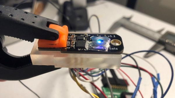
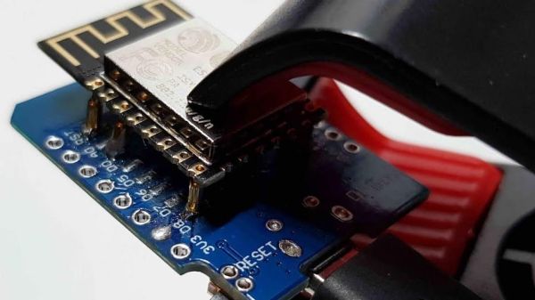
Flashing the AiLight bulbs is easy enough, there’s a series of test points right on the face of the PCB that you can hook up to. But if you’re updating more than one of them, you don’t want to have to solder your programmer up to each bulb individually. That’s where the jig comes in. [cperiod] says there are already some 3D printed designs out there, but they proved to be a bit finicky.

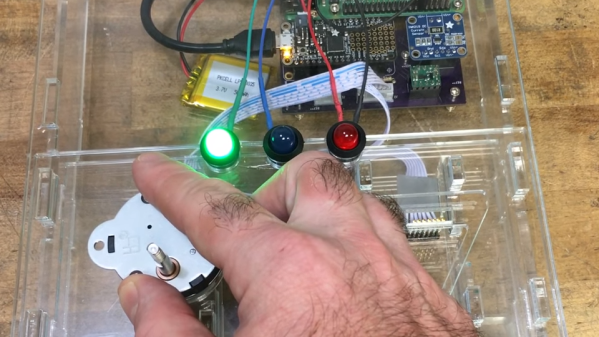
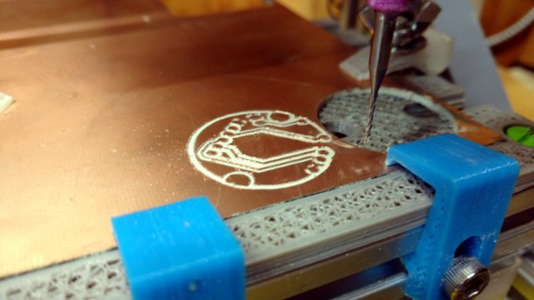
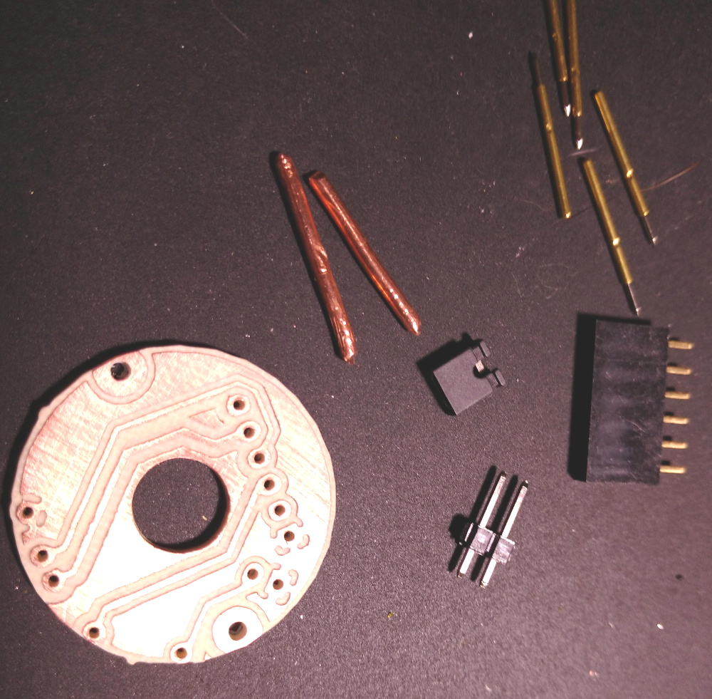
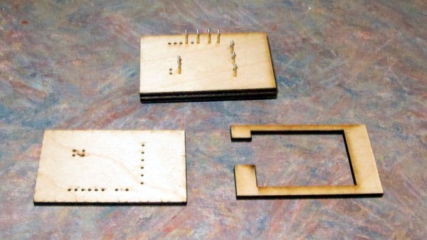
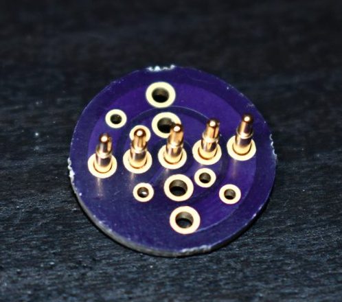
The design that [cperiod] came up with and eventually milled out on a 1610 CNC router is quite simple. It’s effectively just a holder to keep the five pogo pins where they need to be, and a jumper that lets you toggle the chip’s programming mode (useful for debugging).

The neat trick here are the “alignment pins”, which are actually two pieces of 14 gauge copper wire that have had their ends rounded off. It turns out these will slip perfectly into holes on the AliLight PCB, ensuring that the pogo pins end up on target. It works well enough that you can hold the bulb and jig in one hand while programming, it just needs a little downwards pressure to make good contact.

We’ve previously seen how easily you can replace the firmware on some of these ESP8266 bulbs. While there’s certainly a downside to these bulbs being so simple to modify, it’s hard to deny their hackability makes them very appealing for anyone looking to roll their own network-controlled lighting system.

Magnetic Attraction Of Microduino MCookie Modules

We’ve seen countless different robot kits promoted for STEM education, every one of which can perform the robotic “Hello World” task of line following. Many were in attendance at Maker Faire Bay Area 2019 toiling in their endless loops. Walking past one such display by Microduino, Inc. our attention was caught by a demonstration of their mCookie modules in action: installing a peripheral module took less than a second with a “click” of magnets finding each other.

Many Arduino projects draw from an ecosystem of Arduino shields. Following that established path, Microduino had offered tiny Arduino-compatible boards and peripherals which connected with pins and headers just like their full-sized counterparts. Unfortunately their tiny size also meant their risk of pin misalignment and corresponding damage would be higher as well. mCookie addresses this challenge by using pogo pins for electrical contacts, and magnets to ensure proper alignment. Now even children with not-quite-there-yet dexterity can assemble these modules, opening up a market to a younger audience.

Spring loaded electric connections are a popular choice for programming jigs, and we’ve seen them combined with magnets for ideas like modular keyboards, and there are also LittleBits for building simple circuits. When packaged with bright colorful LEGO-compatible plastic mounts, we have the foundation of an interesting option for introductory electronics and programming. Microduino’s focus at Maker Faire was promoting their Itty Bitty Buggy, which at $60 USD is a significantly more affordable entry point to intelligent LEGO creations than LEGO’s own $300 USD Mindstorm EV3. It’ll be interesting to see if these nifty mCookie modules will help Microduino differentiate themselves from other LEGO compatible electronic kits following a similar playbook.

Laser Cutting Wooden Pogo Pin Test Jigs

Now as far as problems go, selling so many products on Tindie that you need to come up with a faster way to test them is a pretty good one to have. But it’s still a problem that needs solving. For [Eric Gunnerson] the solution involved finding a quick and easy way to produce wooden pogo test jigs on his laser cutter, and we have a feeling he’s not the only one who’ll benefit from it.

The first step was exporting the PCB design from KiCad into an SVG, which [Eric] then brought into Inkscape for editing. He deleted all of the traces that he wasn’t interested in, leaving behind just the ones he wanted to ultimately tap into with the pogo pins. He then used the Circle tool to put a 0.85 mm red dot in the center of each pad.

You’re probably wondering where those specific parameters came from. The color is easy enough to explain: his GlowForge laser cutter allows him to select by color, so [Eric] can easily tell the machine to cut out anything that’s red. As for the size, he did a test run on a scrap of wood and found that 0.85 mm was the perfect dimensions to hold onto a pogo pin with friction.

[Eric] ran off three identical pieces of birch plywood, plus one spacer. The pogo pins are inserted into the first piece, the wires get soldered around the back, and finally secured with the spacer. The whole thing is then capped off with the two remaining pieces, and wrapped up in tape to keep it together.

Whether you 3D print one of your own design or even modify a popular development board to do your bidding, the test jig is invaluable when you make the leap to small scale production.

Breakout Board Becomes Pogo Pin Programmer

Making a programming jig becomes exponentially more difficult after two pins and who would even consider building one if they were not setting up more than twenty boards? If it were easy for novices to construct jigs, we might all have a quiver of them on the shelf next to our microprocessors. Honestly, a tackle box full of homemade programming fixtures sounds pretty chic. The next advantage to ditching the demo boards is that bare processors take up less room and don’t draw power for unnecessary components like unused voltage regulators and LEDs. [Albert David] improves the return-on-time-investment factor by showing us how to repurpose a WeMos board to program a bare ESP8266 module.

[Albert]’s concept can apply to many other surface-mount chips and modules. The first step is to buy a demo board which hosts a programmable part and remove that part. Since you’ve exposed some solder pads in the process, put pogo pins in their place. Pogo pins are small spring-loaded probes that can be surface mounted or through-hole. We’ve used them for programming gorgeous badges and places where the ESP8266 has already been installed. When you are ready to install your software, clamp your Franken-porcupine to the controller and upload like normal. Rinse, wash, repeat. We even get a view of the clamp [Albert] uses.

Lightsaber Uses Pogo Pins To Make Assembly A Breeze

There was an endless supply of fantastic projects at Supercon this year, but one whose fit and finish really stood out was [Scott]’s lightsaber. If you were walking around and saw someone with a very bright RGB device with a chromed-out handle hanging off their belt it was probably this, though it may have been hard to look at directly. On the outside, the saber looks like a well-polished cosplay prop, and it is! But when Scott quickly broke down the device into component pieces it was apparent that extra care had been put into the assembly of the electronics.

Like any good lightsaber replica the blade is lit, and wow is it bright. The construction is fairly simple, it’s a triplet of WS2812B LED strips back to back on a triangular core, mounted inside a translucent polycarbonate tube with a diffuser. Not especially unusual. But the blade can be popped off the hilt at a moments notice for easy transport and storage, so the strips can’t be soldered in. Connectors would have worked, but who wants flying wires when they’re disconnecting their lightsaber blade. The answer? Pogo pins! Scott runs the power, ground, and data lines out of the strips and into a small board with slip ring-style plated rings. On the hilt, there is a matching array of pogo pins to pass along power and data. The data lines from all the strips are tied together minimizing the number of connections to make, and the outer two power rings have more than one pin for better current-carrying capacity. A handy side effect is that there is nowhere on the blade where there aren’t LEDs; the strips go down to the very end of the blade where it meets the main board inside the hilt.

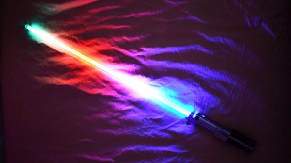
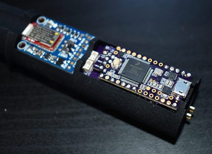
The hilt is filled with an assembly of 18650’s and a Teensy mounted with a custom shield, all fit inside a printed midframe. The whole build is all about robust design that’s easy to assemble. The main board is book-ended by perpendicular PCBs mounted to the ends, one at the top to connect to the blade and one at the bottom to connect to a speaker. Towards the bottom there is space for an optional Bluetooth radio to allow remote RGB control.

Scott is selling this as a product but also provides detailed instructions and parts lists for each component. Assembly instructions for the blade are here. The hilt is here. And pogo adapters are on OSH Park here. An overview of the firmware with links to GitHub is here. Check out a walkthrough of the handle assembly and blade attachment after the break!

Continue reading “Lightsaber Uses Pogo Pins To Make Assembly A Breeze”

An SLA-Printed Pogo Pin Programming Jig

If you have a microcontroller to program, it can be an easy enough process to hook up a serial lead and perform the task. If however you have hundreds of microcontrollers on PCBs to program, connecting that lead multiple times becomes an impossibility. In manufacturing environments they have pogo pin jigs, an array of spring-loaded pins carrying the programming signals that line up perfectly with the appropriate pads on a PCB places on top of it.

[Conor Patrick] is working on an upgrade to the U2F Zero 2-factor authentication token, and he faces exactly this problem of needing to program a lot of boards. His pogo pin jig is very nicely executed, and he’s taken us through his design and manufacture process for it.

Starting with his PCB design in Eagle, he exported it to Fusion 360 in which he was able to create a jig to fit it. Into the jig model he placed the holes for his chosen pogo pins in the appropriate places, before printing it with an SLA 3D printer. He is particularly complementary about the pins themselves, a solder bucket design that comes from mill-Max, and was sourced via DigiKey.

The proof of the pudding is in the eating, and happily when his completed jig received its first board, everything worked as planned and the programming proceeded flawlessly. We’ve shown you other pogo pin jigs, but this one is particularly nicely executed.

A Peek Into A Weed-Eating Robot’s Test Fixtures

When it comes to production, fast is good! But right the first time is better. Anything that helps prevent rework down the line is worth investing in. Some of the best tools to catch problems are good test fixtures. The folks at Tertill (a solar-powered robot for killing weeds that kickstarted last year) took the time to share two brief videos of DIY test fixtures they use to test components before assembly.

The videos are short, but they demonstrate all the things that make a good test: on the motor tester there are no connectors or wires to fiddle with, the test starts automatically, and there is clear feedback via prominent LEDs. The UI board tester also starts automatically and has unambiguous LED feedback, and sports a custom board holder with a recess just the right shape for the PCB. Once the board is in, the sled is pushed like a drawer to make contact with the test hardware and begin the test. The perfectly formed recesses in both units serve another function as well; they act as a go/no-go test for the physical shape of the components and contacts being tested.

Both videos are embedded below; and while there isn’t much detail on the actual test hardware, we do spy a Raspberry Pi and at least two Adafruit logos among other hacker-familiar elements like laser-cut acrylic, 3D printed plastic, pogo pins, and a PVC junction box.

Continue reading “A Peek Into A Weed-Eating Robot’s Test Fixtures”