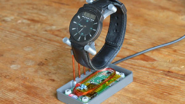
You can win any argument about the time when you have a radio controlled watch. Or, at least, you can if there’s any signal. [Henner Zeller] lives in a place where there is no reception of the DCF77 signal that his European wristwatch expects to receive. Consequently, he decided to make his own tiny transmitter, which emulates the DCF77 signal and allows the watch to synchronise.
A Raspberry Pi Zero W is the heart of the transmitter, and [Henner] manages to coax it into generating 77500.003Hz on a GPIO pin – close enough to the 77.5kHz carrier that DCF77 uses. The signal is AM, and transmits one bit/s, repeating every minute. A second GPIO performs the required attenuation, and a few loops of wire are sufficient for an antenna which only needs to work over a few inches. The Raspberry Pi syncs with NTP Stratum 1 servers, which gives the system time an accuracy of about ±50ms. The whole thing sits in a slick 3D printed case, which provides a stand for the watch to rest on at night; this means that every morning it’s synchronised and ready to go.
[Henner] also kindly took the time to implement the protocols for WWVB (US), MSF (UK) and JJY (Japan). This might be just as well, given that we recently wrote about the possibility of WWVB being switched off. Be sure to check the rules in your area before giving this a try.
We’ve seen WWVB emulators before, like this ATtiny45 build, but we love that this solution is an easy command line tool which supports many geographical locations.
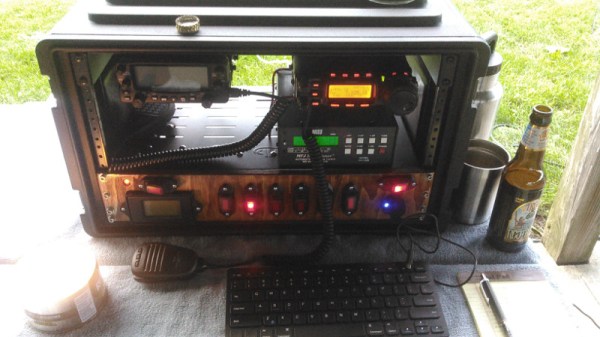
With any hobby, it’s easy for things to get out of hand. Equipment can get scattered around the house, chargers lost in the car while cables languish in the shed… but it doesn’t have to be this way. With a go-bag or go-box, everything required is kept together in a ready-to-go condition. Heading out for a day of filming? Grab the go-bag and you’re all set. [oliverkrystal] wanted to apply this to a ham radio setup, and built this ham shack-in-a-box.
Wanting to use proven components and keep things rugged and usable, the build starts with a 6U-sized plastic rack mount case. This saves weight over plywood versions and is nice and tough. A combination of off-the-shelf rack mount parts and 3D printed pieces are brought together to make it all happen. [oliverkrystal]’s printed cable organisers are a particular treat, and something we think could help a lot of builds out there.
It all comes together as an impressive self-contained unit with two radios, an antenna tuner, in-built illumination and other useful features. No longer does one have to scramble around preparing gear for the weekend’s hamventures – grab the box and you’re ready to go!
Software defined radio picked up a lot of popularity when it was discovered that cheap USB TV tuners were functional bits of hardware that could become SDRs. It’s the software that makes this possible, and when it comes to SDR software, there’s no better tool than GNU Radio. For this week’s Hack Chat we’re going to sit down with some of the people behind this awesome software tool and pick their brains.
Our guests for this week’s Hack Chat will be Derek Kozel and Nate Temple, officers of the GNU Radio project. They’re also organizers of this year’s GNU Radio Conference. Also joining in on the Hack Chat will be Martin Braun, community manager, PyBOMBS maintainer, and GNU Radio Foundation officer.
GNU Radio is perhaps the most important bit of any software defined radio toolchain. This is the software that provides signal processing blocks to implement software defined radios. GNU radio is how you take a TV tuner USB dongle and pull images from satellites. You can use it for simulation, and GNU Radio is widely used by hobbyists, academics, and by people in industry.
For this week’s Hack Chat, we’re going to be talking all about GNU Radio. What can you do with it? Was the interface really inspired by MaxMSP? All that and more in this week’s Hack Chat.
Various bits of hardware that make GNU Radio work
The core process of writing modules
Upcoming features of GNU Radio
You are, of course, encouraged to add your own questions to the discussion. You can do that by leaving a comment on the GNU Radio Hack Chat Event Page and we’ll put that in the queue for the Hack Chat discussion.
Once relegated to the proverbial Linux loving Firefox user, ad blocking has moved into public view among increased awareness of privacy and the mechanisms of advertising on the internet. At the annual family gathering, when That Relative asks how to setup their new laptop, we struggle through a dissertation on the value of ad blockers and convince them to install one. But what about mediums besides the internet? Decades ago Tivo gave us one button to jump through recorded TV. How about the radio? If available, satellite radio may be free of The Hated Advertisement. But terrestrial radio and online streams? [tomek] wasn’t satisfied with an otherwise sublime experience listening streaming Polish Radio Three and decided to build a desktop tool to detect and elide ads from the live audio stream.
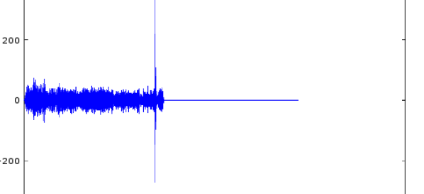
[tomek] was aware of this hip knowledge domain called Digital Signal Processing but hadn’t done any of it themselves. Like many algorithmic problems the first step was to figure out the fastest way to bolt together a prototype to prove a given technique worked. We were as surprised as [tomek] by how simple this turned out to be. Fundamentally it required a single function – cross-correlation – to measure the similarity of two data samples (audio files in this case). And it turns out that Octave provides it in the box. After snipping the start-of-ad jingle out of a sample file and comparing it to a radio program [tomek] got the graph at the left. The conspicuous spike is the location of the jingle in the audio file.
At this point all that was left was packaging it all into a one click tool to listen to the radio without loading an entire analysis package. Conveniently Octave is open source software, so [tomek] was able to dig through its sources until they found the bones of the critical xcorr() function. [tomek] adapted their code to pour the audio into a circular buffer in order to use an existing Java FFT library, and the magic was done. Piping the stream out of ffmpeg and into the ad detector yielded events when the given ad jingle samples were detected.
[tomek] packaged that tool into a standalone executable, but the gem here is the followup post. After removing ads in the online stream they adapted a RaspberryPi to listen to an FM receiver and remote control their Yamaha tuner over the network. So when the tuner is playing Radio Three the Pi notices and ducks the audio appropriately to avoid those pesky ads. Video of this after the break.
Buried on page 25 of the 2019 budget proposal for the National Institute of Standards and Technology (NIST), under the heading “Fundamental Measurement, Quantum Science, and Measurement Dissemination”, there’s a short entry that has caused plenty of debate and even a fair deal of anger among those in the amateur radio scene:
NIST will discontinue the dissemination of the U.S. time and frequency via the NIST radio stations in Hawaii and Ft. Collins, CO. These radio stations transmit signals that are used to synchronize consumer electronic products like wall clocks, clock radios, and wristwatches, and may be used in other applications like appliances, cameras, and irrigation controllers.
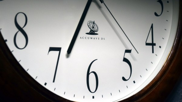
The NIST stations in Hawaii and Colorado are the home of WWV, WWVH, and WWVB. The oldest of these stations, WWV, has been broadcasting in some form or another since 1920; making it the longest continually operating radio station in the United States. Yet in order to save approximately $6.3 million, these time and frequency standard stations are potentially on the chopping block.
What does that mean for those who don’t live and breathe radio? The loss of WWV and WWVH is probably a non-event for anyone outside of the amateur radio world. In fact, most people probably don’t know they even exist. Today they’re primarily used as frequency standards for calibration purposes, but in recent years have been largely supplanted by low-cost oscillators.
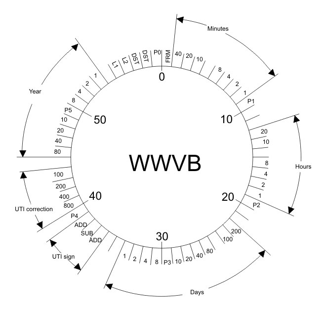
But WWVB on the other hand is used by millions of Americans every day. By NIST’s own estimates, over 50 million timepieces of some form or another automatically synchronize their time using the digital signal that’s been broadcast since 1963. Therein lies the debate: many simply don’t believe that NIST is going to shut down a service that’s still actively being used by so many average Americans.
The problem lies with the ambiguity of the statement. That the older and largely obsolete stations will be shuttered is really no surprise, but because the NIST budget doesn’t specifically state whether or not the more modern WWVB is also included, there’s room for interpretation. Especially since WWVB and WWV are both broadcast from Ft. Collins, Colorado.
What say the good readers of Hackaday? Do you think NIST is going to take down the relatively popular WWVB? Are you still using devices that sync to WWVB, or have they all moved over to pulling their time down over the Internet? If WWVB does go off the air, are you prepared to setup your own pirate time station?
Even though it’s now a forgotten afterthought in the history of broadcasting technology, we often forget how innovative the TiVo was. All this set-top box did was connect a hard drive to a cable box, but the power was incredible: you could pause live TV. You could record shows. You could rewind TV. It was an incredible capability, that no one had ever seen before. Of course, between Amazon and Netflix and YouTube, no one watches TV anymore, and all those platforms have a pause button, but the TiVO was awesome.
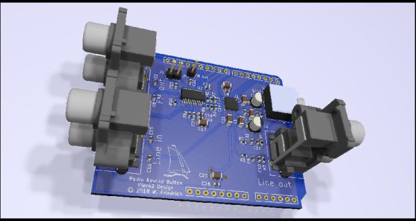
There is one bit of broadcasting that still exists. Radio. For his Hackaday Prize entry, [MagicWolfi] is bringing the set-top box to radio. He’s invented the Radio Rewind Button, and it does exactly what you would expect: it rewinds live radio a few minutes.
To have a pause or rewind button on a TV or radio, the only real requirement is a bunch of memory. The TiVO did this with a hard drive, and [MagicWolfi] is doing this with 256 MB of SDRAM. That means he needs to access a ton of RAM, and for that he’s turning to the Digilent ARTY S7 board. Yes, it’s an FPGA, but actually a fairly simple solution to the problem.
The rest of the circuit is an FM receiver chip and an I2S audio codec on an Arduino-shaped daughterboard. The main controller for this project is a big red button that will simply rewind the audio stream a few minutes. There’s no telling exactly how long [MagicWolfi] will be able to rewind the audio stream, but 256 MB is a ton in the audio world.
If you are in any way connected with radio, you will have encountered the low pass filter as a means to remove unwanted harmonics from the output of your transmitters. It’s a network of capacitors and inductors usually referred to as a pi-network after the rough resemblance of the schematic to a capital Greek letter Pi, and getting them right has traditionally been something of a Black Art. There are tables and formulae, but even after impressive feats of calculation the result can often not match the expectation.
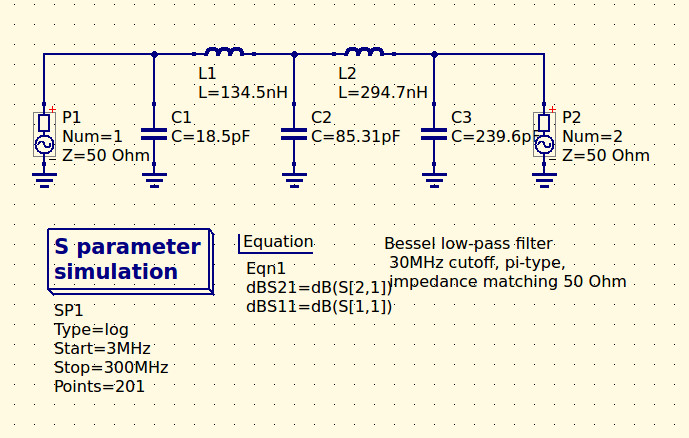
The 30MHz low-pass filter, as QUCS delivered it.
Happily as with so many other fields, in recent decades the advent of affordable high-power computing has brought with it the ability to take the hard work out of filter design, Simply tell some software what the characteristics of your desired filter are, and it will do the rest. The results are good, and anyone can become a filter designer, but as is so often the case there remains a snag. The software calculates ideal inductances and capacitances for the desired cut-off and impedance, and in selecting the closest preferred values we modify the characteristics of the result and possibly even ruin our final filter. So it’s worth taking a look at the process here, and examining the effect of tweaking component values in this way.
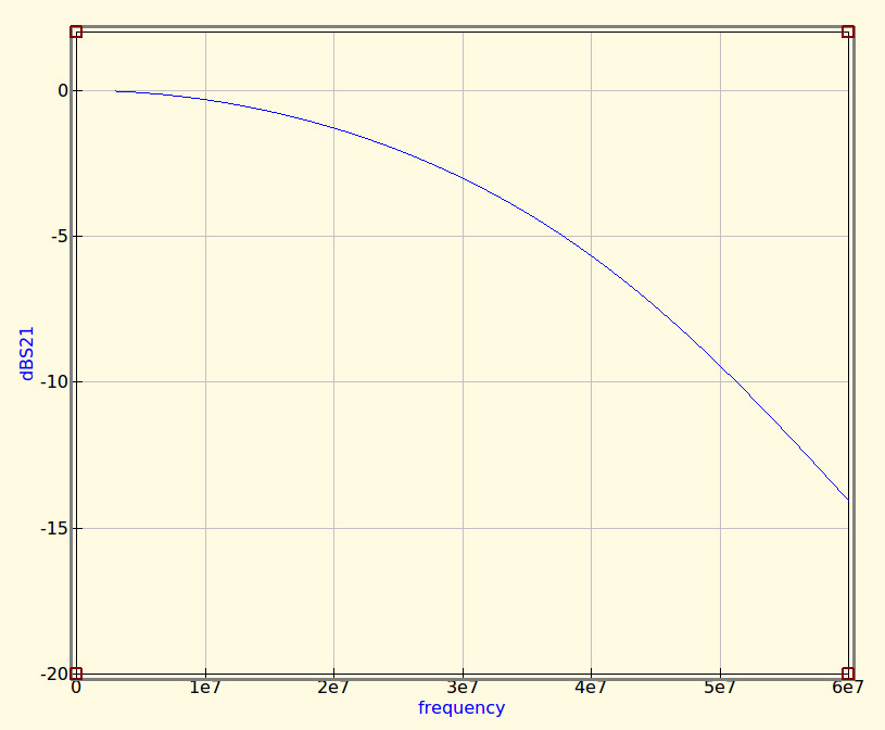
The idealised graph produced by QUCS for our filter.
The filter we’re designing is simple enough, a 5th-order Bessel filter, and the software is the easy-to-use QUCS package on an Ubuntu Linux machine. Plug in the required figures and it spits out a circuit diagram, which we can then simulate to show a nice curve with a 3dB point right on 30MHz. It’s an extremely idealised graph, and experience has taught me that real-world filters using these designs have a lower-frequency cut-off point, but for our purposes here it’s a good enough start.
As previously mentioned, the component values are not preferred ones from a commercially available series, so I can’t buy them off the shelf. I can wind my own inductors, but therein lies a whole world of pain of its own and I’d rather not go there. RS, Mouser, Digikey, Farnell et al exist to save me from such pits of electronic doom, why on earth would I do anything else but buy ready-made?
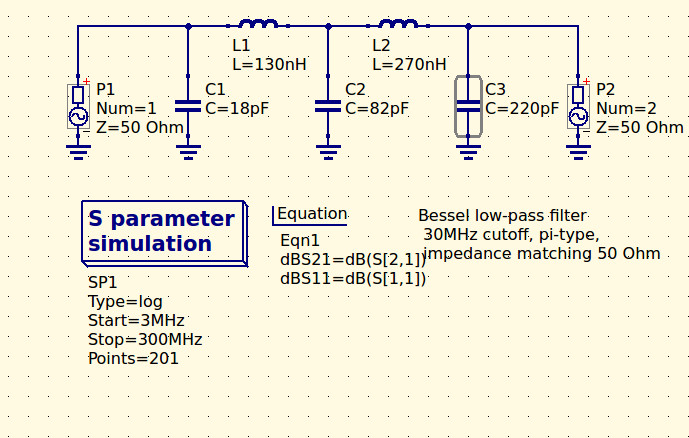
My revised filter circuit with off-the-shelf component values.
So each of the components in the above schematic needs moving up or down a little way to a preferred value. What effect will that have on the performance of my filter? Changing each value and re-running the simulation shows us the graph changing subtly each time, and it can sometimes be a challenge to adjust them without destroying the filter entirely. Particularly with the higher-order filters with more components in the network you can observe the effect of individual components on the gradient at different parts of the graph, but as a rule of thumb making values higher reduces the cut-off frequency and making them lower increases it. In my case I always pick higher values for that reason: my nearest harmonic I wish to filter is at double the frequency so I have quite some headroom to play with.
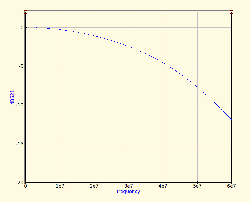
The revised curve from the filter with preferred values.
Having replaced my component values with preferred ones I can run the simulation again, and I can see from the resulting graph that I’ve been quite fortunate in not damaging its characteristics too much. As expected the cut-off frequency has shifted up a little, but the same curve shape has been preserved without any ripples appearing or it being made shallower.
If I were using this filter with a real transmitter I would ensure that I designed it with a cut-off at least a quarter higher than the transmission frequency. In practice I find the cut-off to be sharper and lower than the simulation leads one to expect, and for example, were I to use this one with a 30 MHz transmitter I’d find it attenuated the carrier by more than I’d consider acceptable. It must also be admitted that changing the component values in this way will also change the impedance of the filter from the calculated 50 ohms, however in practice this does not seem to be significant enough to cause a problem as long as the value changes are modest.
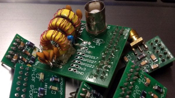
We haven’t made this filter, but in the past we’ve featured another one I did make, and by coincidence it was in the same frequency range. When I wrote a feature on automating oscilloscope readings, the example I used was the characterisation of a 7th-order 30 MHz low-pass filter. It might even be one of the ones in the header image, pulled from my random bag of filter boards for the occasion.


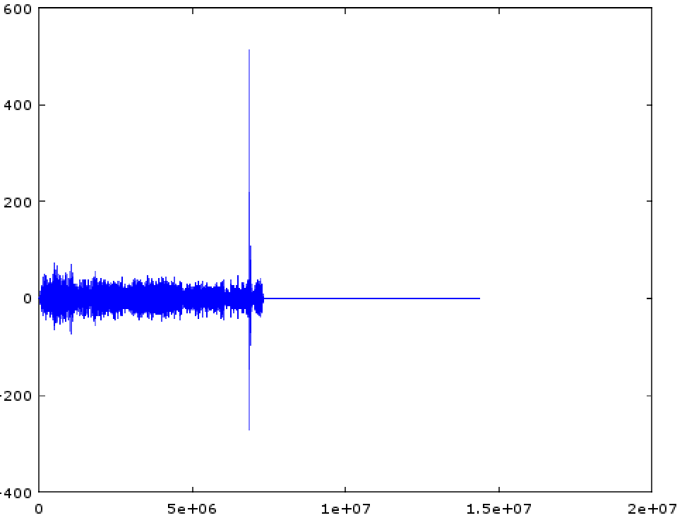 [tomek] was aware of this hip knowledge domain called Digital Signal Processing but hadn’t done any of it themselves. Like many algorithmic problems the first step was to figure out the fastest way to bolt together a prototype to prove a given technique worked. We were as surprised as [tomek] by how simple this turned out to be. Fundamentally it required a single function – cross-correlation – to measure the similarity of two data samples (audio files in this case). And it turns out that
 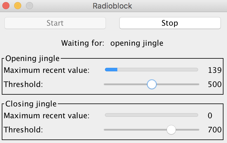 At this point all that was left was packaging it all into a one click tool to listen to the radio without loading an entire analysis package. Conveniently Octave is open source software, so [tomek] was able to dig through its sources until they found the bones of the critical xcorr() function. [tomek] adapted their code to pour the audio into a circular buffer in order to use an existing Java FFT library, and the magic was done. Piping the stream out of ffmpeg and into the ad detector yielded events when the given ad jingle samples were detected.