Annoying though they can be, if you play any kind of instrument, you will definitely benefit from using a metronome. While many of them thock or otherwise tock, the VRRVRR metronome from [Turi] works a little differently.
 In addition to flashing LEDs, the VRRVRR contains a small vibrating motor. If you’re wondering about the name, it comes from the fact that it vibrates and makes a sort of vrr vrr sound. Need to be quiet? A small switch on the side shuts off the vibrations.
The 4×4 keypad really allowed [Turi] to cram in a bunch of features using both short and long press to do different things. On short press, the digits set the tempo. When not typing in a tempo, zero can be used to enter a tempo by tapping. The letters load preset tempos, and the +/- keys increase and decrease it.
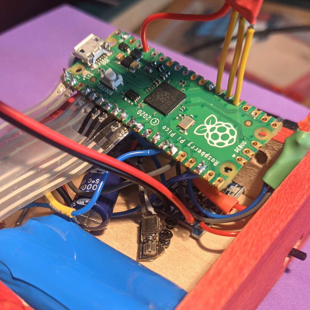
Inside the basswood enclosure is a Raspberry Pi Pico, the vibration motor, and various other bits and bobs that make it go. There’s even an LED to indicate that it’s time to charge the lithium battery. If you want to build your own, head on over to GitHub, but be sure to take the brief VRRVRR tour after the break.
We don’t see too many metronomes around here, but we do have this nice teardown to offer you.
Continue reading “Metronome Flashes And Vibrates To The Beat”