Once upon a time, if you wanted to generate some waveforms, you needed to buy an expensive off-the-shelf function generator or whip up a big pile of analog electronics. Not so today, when you can grab a fast microcontroller off the shelf and have it squirt out whatever fancy waves you might desire. That’s just what [rgco] did to build this nifty arbitrary wave generator.
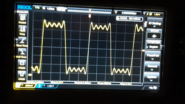
The build improves on prior work by [rgco] with the Arduino Uno, with which they built a device that could output at 381 kilosamples per second, with each sample update taking 42 instruction cycles. Thanks to the Pi Pico’s faster clock speed and certain performance optimizations, they were able to up that to a mighty 125 megasamples per second, using the DMA and PIO subsystems to output a new sample every single clock cycle.
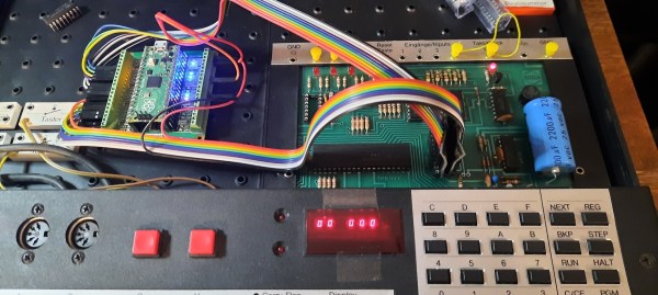
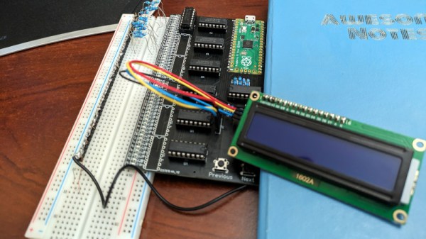
The result is a cheap function generator you can build with a Pi Pico and a handful of resistors, which will probably cost you the grand total of $12. It readily outperforms, at least in regards of speed, devices based on the AD9833 function generator chip, which only runs at 25 megasamples. Plus, that chip can only output sines, triangles, and squares!
Even a passable function generator can be a useful tool to have in the workshop, as we’ve seen before. Video after the break.
Continue reading “Arbitrary Wave Generator For The Raspberry Pi Pico”