[James] has been working with GameCubes, emulators, and Animal Crossing for a while now, and while emulators are sufficient, he’d like to play on real hardware. This means he needs to write to a GameCube memory card. While there are a few options to do this, they either require a Wii or hardware that hasn’t been made in a decade. The obvious solution to this problem is to reverse engineer the GameCube memory card to read and write the memory with a Raspberry Pi.
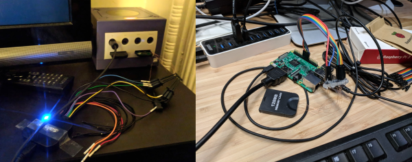
There’s an incredible amount of unofficial documentation for every console, and [James] stumbled upon a GC-Forever forum post that describes the electrical signals inside the GameCube memory card. There’s your standard compliment of power and ground pads, along with a DI, DO, CS, Clk, and an INT pin. [James] broke out the magnet wire and soldered up a pin header to these cards. Data was then captured with a Salae logic analyzer, and lo and behold, it looked like a standard SPI protocol.
With the low-level protocol worked out, [James] checked out the Yet Another GameCube Documentation to get the main functions allowed through the SPI bus. The ‘read block’, for instance, starts off with 0x52 and an address offset. A little bit of Python on a Raspberry Pi meant [James] could read and write the entire GameCube memory card. Right now the code is a little rough, but all the work is available should you want to edit your Animal Crossing save with a Raspberry Pi.
This work follows [James]’ earlier work on getting into the debug menu of Animal Crossing, allowing him to add items to his inventory. With this latest advancement, it’s only a matter of time before we plug Raspberry Pis directly into a GameCube.


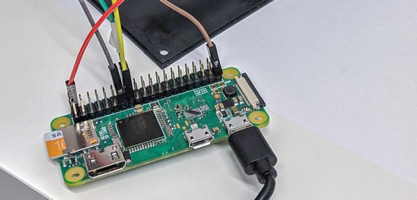
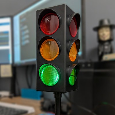 The hardware for this build is a traffic light table lamp available on Amazon for twenty bucks. Inside this traffic light, you get a PCB with three LEDs and a small microcontroller to control the LEDs. The microcontroller isn’t used in this case, instead the microcontroller is removed and a few wires are soldered up to the base of the transistors used to drive the LEDs. The other ends of these wires are attached to a trio of pins on a Raspberry Pi Zero W, giving this traffic light table lamp Linux and a connection to the Internet.


