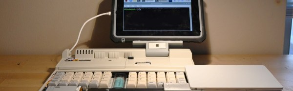
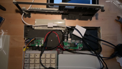
Tiny Raspberry Pi Mac Nails The Apple Aesthetic

We know that some in the audience will take issue with calling a Raspberry Pi in a 3D-printed case the “World’s Smallest iMac”, but you’ve got to admit, [Michael Pick] has certainly done a good job recreating the sleek look of the real hardware. While there might not be any Cupertino wizardry under all that PLA, it does have a properly themed user interface and the general aversion to external ports and wires that you’d expect to see on an Apple desktop machine.

The clean lines of this build are made possible in large part by the LCD itself. Designed specifically for the Raspberry Pi, it offers mounting stand-offs on the rear, integrated speakers, a dedicated 5 V power connection, and a FFC in place of the traditional HDMI cable. All that allows the Pi to sit neatly on the back of the panel without the normal assortment of awkward cables and adapters going in every direction. Even if you’re not in the market for a miniature Macintosh, you may want to keep this display in mind for your future Pi hacking needs.

Well, that’s one way to do it.

Despite this clean installation, the diminutive Raspberry Pi was still a bit too thick to fit inside the 3D-printed shell [Michael] designed. So he slimmed it down in a somewhat unconventional, but admittedly expedient, way. With a rotary tool and a steady hand, he simply cut the double stacked USB ports in half. With no need for Ethernet in this build, he bisected the RJ-45 connector as well. We expect some groans in the comments about this one, but it’s hard to argue that this isn’t a hack in both the literal and figurative sense.

We really appreciate the small details on this build, from the relocated USB connectors to the vent holes that double as access to the LCDs controls. [Michael] went all out, even going so far as to print a little insert for the iconic Macintosh logo on the front of the machine. Though given the impressive work he put into his miniature “gaming PC” a couple months back, it should come as no surprise; clearly this is a man who takes his tiny computers very seriously.

Continue reading “Tiny Raspberry Pi Mac Nails The Apple Aesthetic”

You’ve Never Seen This RetroPie Emulator Console: Watermelon

The Raspberry Pi is a hugely popular platform for emulating older consoles, with the RetroPie framework making it easy to get started in no time at all. Often, these single board computers get built into fun arcade boxes or replica console shells to add to the charm. That’s all been done, so instead, [Cedishappy] decided to go in his own direction – resulting in the wonderful Watermelon Gameboy.

What sounds like a trivial exercise of building a RetroPie rig in a unique enclosure actually comes with some engineering challenges. The basics are all pretty standard – GPIO pins interfacing buttons, a speaker and the screen, emulating a Gameboy Advance. But the mechanical implementation is more complex. The watermelon is first cut open, having its red flesh removed, leaving just the rind. Paper and cardboard templates are then used to make holes for the buttons and screen. Unfortunately, hot glue doesn’t work on watermelon, so instead, toothpicks were used to hold the screen and speaker in place. To protect the electronics from the moist melony environment inside, clear food wrap was applied to the Raspberry Pi and other components where needed.

[Cedishappy] goes above and beyond with the project video charmingly showing the reactions of bystanders to the contextually confusing game system. The combination of electronics with fruit and vegetables is an area we don’t see explored often enough; our own [Mike Szczys] built a magnificent LED Jack-o-Lantern that really looks the business. Video after the break.

Continue reading “You’ve Never Seen This RetroPie Emulator Console: Watermelon”

Sunrise, Sunset, Repeat

Sunrises and sunsets hardly ever disappoint. Still, it’s difficult to justify waking up early enough to catch one, or to stop what you’re doing in the evening just to watch the dying light. If there’s one good thing about CCTV cameras, it’s that some of them are positioned to catch a lovely view of one of the two, and a great many of them aren’t locked down at all.

[Dries Depoorter] found a way to use some of the many unsecured CCTV cameras around the world for a beautiful reason: to constantly show the sun rising and setting. Here’s how it works: a pair of Raspberry Pi 3B + boards pull the video feeds and display the sunrise/sunset location and the local time on VFD displays using an Arduino Nano Every. There isn’t a whole lot of detail here, but you can probably get the gist from the high-quality pictures.

If you wanted to recreate this for yourself, we might know where you can find some nice CCTV camera candidates. Just look through this dystopian peephole.

Thanks for the tip, [Luke]!

Raspberry Pi Makes A Practical Tricorder

What do you get when you add a thermal camera, a software-defined radio dongle, and a battery to a Raspberry Pi? If you are [saveitforparts] you make a tricorder for sniffing radio signals and viewing heat signatures. He admits, the videos (see below) aren’t exactly a “how-to” but it will still give you some ideas for your next build.

You can sense the frustration with some Linux configuration issues, but [saveitforparts] admits he isn’t a Linux or Raspberry Pi guru. Version 1 seemed to be a bit of a prototype, but version 2 is more polished. We still aren’t sure we’d see Spock carrying a case like that, but some 3D printing could spiff that right up.

Of course, a real tricorder is a McGuffin that does whatever the plot calls for. This one is a bit more practical, but it can monitor thermal and RF energy and could accommodate more sensors. This is a great example of a project that would have been very hard to do in the past but is much easier today. The availability of cheap computers and ready-made modules along with associated software open up many possibilities.

If you want to do your own Tricorder hacking you could take over a commercial model. Then again, there’s an official replica on its way that seems like it might have some similar features.

Continue reading “Raspberry Pi Makes A Practical Tricorder”

Student Rover Explores The Backyard In Tribute

Three students were a little sad when NASA’s Opportunity rover went silent after 15 years on the Martian surface. So they decided to build their own rover inspired by Opportunity to roam their backyards using an off-the-shelf robot chassis, a Raspberry Pi, and the usual list of parts like motors, H-bridges, and batteries.

Like the real rover, the vehicle uses a rocker-bogie system, although it is a little less complex than the version NASA sent blasting off towards the Red Planet. The plucky vehicle comes complete with miniature solar panels to recharge its onboard battery, courtesy of some dollar-store garden lights. A pair of videos after the break show how the rover is controlled, as well as the view sent back from its onboard camera.

The rover ran a simulated Mars mission as part of a school project where it had to find an object and transmit an image of it back to home base, and by the looks of it, is was a rousing success. But the young explorers aren’t resting on their laurels, and are already working on a second version of their exploration vehicle that can operate in inclement weather and includes some new tools such as a robotic arm and infrared illumination for low-light imaging.

We’ve seen plenty of Mars rover clones in the past, but there’s always room for more. Of course, if you’re looking for something a bit easier to start with, you can always go the LEGO route.

Continue reading “Student Rover Explores The Backyard In Tribute”

Rack ’em Stack ’em Raspberry Pi Controller Board

It isn’t that hard to assemble an array of Raspberry Pi boards and there are several reasons you might want to do so. The real trick is getting power to all of them and cooling all of them without having a mess of wires and keeping them all separated. The ClusterCTRL stack lets you stack up to five Raspberry Pi boards together. The PCB aligns vertically along the side of the stack of Pis with sockets for each pin header. Using a single 12 to 24V supply, it provides power for each board, a USB power connection, and provisions for two fans. There is also a USB port to control the fans and power.

There’s also a software component to deliver more granular control. Without using the software, the PI’s power on in one second and monitor a GPIO pin to control the fans. With the software, you can turn on or off individual nodes, gang the two fans to turn on together, and even add more stacks.

There is a case that you can print from STL files, although you can buy them preprinted on the Tindie listing where the bulk of information on ClusterCTRL is found. You could also have a 3D printing vendor run off a copy for you if you’d rather.

The power supply is a 10A 5.1V DC to DC converter. That works out to 2A per Pi and 51W total. The power supply for the input, then, needs to be enough to cover 51W, the power for the fans, and some overhead for regulator inefficiency and other small overhead.

We’ve seen a lot of Pi clusters over the years including one that is a good learning tool for cluster management. Of course, there’s always the Oracle cluster with 1,060 boards, which is going to take a bigger power supply.

Folding Raspberry Pi Enclosure Prints In One Piece, No Screws In Sight

[jcprintnplay] has challenged himself to making Raspberry Pi cases in different ways, and his Fold-a-Pi enclosure tries for a “less is more” approach while also leveraging the strong points of 3D printing. The enclosure prints as a single piece in about 3 hours, and requires no additional hardware whatsoever.

The design requires no screws or other fasteners, and provides a mounting hole for a fan as well as some holes for mounting the enclosure itself to something. All the ports and headers are accessible, and the folding one-piece design is not just a gimmick; in a workshop situation where the Pi needs to be switched out or handled a lot, it takes no time at all to pop the Raspberry Pi in and out of the enclosure.

Microsoft’s 3D Builder has a pretty useful measurement tool for STLs.

[James] points out that the trick with a print-in-place hinge like this is leaving enough space between the parts so that the two pieces aren’t fused together, but not so much space that the print fails. He doesn’t go into detail about how much space worked or didn’t work, but an examination of the downloadable model shows that the clearance used looks like 0.30 mm, intended to be printed with a 0.4 mm nozzle.

[James] also demonstrates the value of being able to do quick iterations on a design when prototyping. In a video (embedded below) The first prototype had the hinge not quite right. In the second prototype there was a lack of clearance when closing. The third one solved both and shows the final design.

Continue reading “Folding Raspberry Pi Enclosure Prints In One Piece, No Screws In Sight”