The BNC Connector And How It Got That Way

When I started working in a video production house in the early 1980s, it quickly became apparent that there was a lot of snobbery in terms of equipment. These were the days when the home video market was taking off; the Format War had been fought and won by VHS, and consumer-grade VCRs were flying off the shelves and into living rooms. Most of that gear was cheap stuff, built to a price point and destined to fail sooner rather than later, like most consumer gear. In our shop, surrounded by our Ikegami cameras and Sony 3/4″ tape decks, we derided this equipment as “ReggieVision” gear. We were young.

For me, one thing that set pro gear apart from the consumer stuff was the type of connectors it had on the back panel. If a VCR had only the bog-standard F-connectors like those found on cable TV boxes along with RCA jacks for video in and out, I knew it was junk. To impress me, it had to have BNC connectors; that was the hallmark of pro-grade gear.

I may have been snooty, but I wasn’t really wrong. A look at coaxial connectors in general and the design decisions that went into the now-familiar BNC connector offers some insight into why my snobbery was at least partially justified.

Continue reading “The BNC Connector And How It Got That Way”

Fully 3D Printed And Metalized Horn Antennas Are Shiny And Chrome

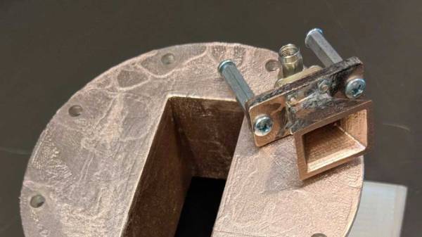
We’ve seen our share of 3D printed antennas before, but none as well documented and professionally tested as [Glenn]’s 3D printed and metalized horn antennas. It certainly helps that [Glenn] is the principal engineer at an antenna testing company, with access to an RF anechoic chamber and other test equipment.

Horn antennas are a fairly simple affair, structurally speaking, with a straight-sided horn-shaped “cone” and a receptacle for standardized waveguide or with an appropriate feed, coaxial adapters. They are moderately directional and can cover a wide range of frequencies. These horns are often used in radar guns and as feedhorns for parabolic dishes or other types of larger antenna. They are also used to discover the cosmic microwave background radiation of our universe and win Nobel Prizes.

[Glenn]’s antennas were modeled in Sketchup Make, and those files plus standard STL files are available for download. To create your own horn, print the appropriate file on a normal consumer-grade fused deposition printer. For antennas that perform well in WiFi frequency ranges you may need to use a large-format printer, as the prints can be “the size of a salad bowl”. Higher frequency horns can easily fit on most print beds.

After printing, [Glenn] settled on a process of solvent smoothing the prints, then metalizing them with commonly available conductive spray paints. The smoothing was found to be necessary to achieve the expected performance. Two different paints were tested, with a silver-based coating being the clear winner.

The full write-up has graphs of test results and more details on the process that led to these cheap, printed antenna that rival the performance of more expensive commercial products.

If you’re interested in other types of 3D printed antenna, we’ve previously covered a helical satcom feed, a large discone antenna, and an aluminum-taped smaller discone antenna.
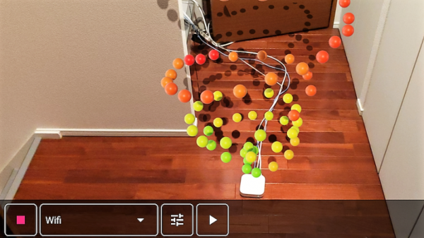
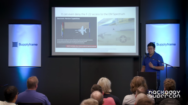
Tearing Into A $1.3 Million Oscilloscope

Most hackers are rankled by those “Warranty Void If Broken” seals on the sides of new test equipment. Even if they’re illegal, they at least put the thought in your head that the space inside your new gear is off-limits, and that prevents you from taking a look at what’s inside. Simply unacceptable.

[Shahriar] has no fear of such labels and tears into just about everything that comes across his bench. Including, most recently, a $1.3 million 110-GHz oscilloscope from Keysight. It’s a teardown that few of us will ever get the chance to do, and fewer still would be brave enough to attempt. Thankfully he does, and the teardown video below shows off the remarkable engineering that went into this monster.

The numbers boggle the mind. Apart from the raw bandwidth, this is a four-channel scope (althought the unit [Shahriar] tested is a two-channel) that doesn’t split its bandwidth across channels. The sampling rate is 256 GS/s and the architecture is 10-bits, so this thing is dealing with 10 terabits per second. We found the extra thick PCBs, which are perhaps 32-layer boards, to be especially interesting, and [Shariar]’s tour of the front end was fascinating.

It all sounds like black magic at first, but he really makes the technology approachable, and his appreciation for fine engineering is obvious. If you’ve got even a passing interest in RF electronics you should check it out. You might want to brush up on microwave topics first, though; this Doppler radar teardown might help.

Continue reading “Tearing Into A $1.3 Million Oscilloscope”

Fail Of The Week: How Not To Design An RF Signal Generator

We usually reserve the honor of Fail of the Week for one of us – someone laboring at the bench who just couldn’t get it together, or perhaps someone who came perilously close to winning a Darwin Award. We generally don’t highlight commercial products in FotW, but in the case of this substandard RF signal generator, we’ll make an exception.

We suppose the fail-badge could be pinned on [electronupdate] for this one in a way; after all, he did shell out $200 for the RF Explorer signal generator, which touts coverage from 24 MHz to 6 GHz. But in true lemons-to-lemonade fashion, the video below he provides us with a thorough analysis of the unit’s performance and a teardown of the unit.

The first step is a look at the signal with a spectrum analyzer, which was not encouraging. Were the unit generating a pure sine wave as it should, we wouldn’t see the forest of spikes indicating harmonics across the band. The oscilloscope isn’t much better; the waveform is closer to a square wave than a sine. Under the hood, he found a PIC microcontroller and a MAX2870 frequency synthesizer, but a conspicuous absence of any RF filtering components, which explains how the output got so crusty. Granted, $200 is not a lot to spend compared to what a lab-grade signal generator with such a wide frequency range would cost. And sure, external filters could help. But for $200, it seems reasonable to expect at least some filtering.

We applaud [electronupdate] for taking one for the team here and providing some valuable tips on RF design dos and don’ts. We’re used to seeing him do teardowns of components, like this peek inside surface-mount inductors, but we like thoughtful reviews like this too.

Continue reading “Fail Of The Week: How Not To Design An RF Signal Generator”

Digital Attenuator Goes From Manual To Arduino Control

[Kerry Wong] comes across the coolest hardware, and always manages to do something interesting with it. His widget du jour is an old demo board for a digital RF attenuator chip, which can pad a signal in discrete steps according to the settings of some DIP switches. [Kerry]’s goal: forget the finger switch-flipping and bring the attenuator under Arduino control.

As usual with his videos, [Kerry] gives us a great rundown on the theory behind the hardware he’s working with. The chip in question is an interesting beast, an HMC624LP4E from Hittite, a company that was rolled into Analog Devices in 2014. The now-obsolete device is a monolithic microwave integrated circuit (MMIC) built on a gallium arsenide substrate rather than silicon, and attenuates DC to 6-GHz signals in 64 steps down to -31.5 dBm. After a functional check of the board using the DIP switches, he whipped up a quick Arduino project to control the chip with its built-in serial interface. It’s just a prototype for now, but spinning the encoder is a lot handier than flipping switches, and once this is boxed up it’ll make a great addition to [Kerry]’s RF bench.

If this video puts you in an RF state of mind, check out some of [Kerry]’s other videos, like this one about temperature-compensated crystal oscillators, or the mysteries of microwave electronics.

Continue reading “Digital Attenuator Goes From Manual To Arduino Control”

These Capacitors Are A Cheap Gimmick

If you search through an electrical engineering textbook, you probably aren’t going to find the phrase “gimmick capacitor” but every old ham radio operator knows about them. They come in handy when you need a very small capacitor of unknown value. For example, if you are trying to balance the stray capacitance in a circuit, you might not know exactly what value you need, but you know it won’t be very much. That’s when you want a gimmick capacitor.

A gimmick capacitor is made by taking two strands of insulated wire and twisting them together; the length and the tightness of the twist determine the capacitance. Tightening or loosening the twist, or trimming some of the wire off, makes it tunable.

These are most commonly found in RF equipment or high-speed logic because of the small capacitance involved — usually about 1 to 2 pF per inch of twist or so. The thicker the insulation, the less capacitance you’ll get, so it is common to use magnet wire or something else with a thin insulating layer. You can take this one step further and decrease the spacing by stripping down one wire as long as it isn’t going to touch anything else.

Obviously, the insulation needs to be good enough for the voltage on them, an important consideration in tube circuits, for instance. But other than that, a gimmick capacitor is a straightforward tool to have in your box of design tricks. Can we take this further? Continue reading “These Capacitors Are A Cheap Gimmick”

Everything You Didn’t Know You Were Missing About Bias Tees

Do you need a bias tee? If you want to put a DC voltage on top of an RF signal, chances are that you do. But what exactly are bias tees, and how do they work?

If that’s your question, [W2AEW] has an answer for you with this informative video on the basics of bias tees. A bias tee allows a DC bias to be laid over an RF signal, and while that sounds like a simple job, theory and practice often deviate in the RF world. The simplest bias tee would have a capacitor in series with the RF input and output to pass AC but block DC from getting out the input, and a DC input with a series inductance to prevent RF from getting into the DC circuit. Practical circuits are slightly more complicated, and [W2AEW] covers all you need to know about how real-world bias tees are engineered. He also gives some use cases for bias tees, from sending DC signals up a feed line to control an antenna tuner or rotator to adding a DC bias to a high-speed serial line.

It’s an interesting circuit, and we learned a lot, which is par for the course with [W2AEW]’s videos. Check out some of his other offerings, like a practical guide to the mysteries of Smith charts, or his visualization of how standing waves work.

Continue reading “Everything You Didn’t Know You Were Missing About Bias Tees”