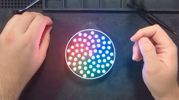
Converting A B&W Enlarger For Colour Analog Photo Printing

[Koraks tinkers] was gifted a gargantuan photographic enlarger, a Durst Laborator 138 s, which is a unit designed specifically for black and white usage only. This was not good enough for [Koraks] so down the rabbit hole of conversion to colour we go! The moral of the story is this: if you can’t find it, build it. The hacker mentality. After wasting time and effort trying to source a period colour head for the thing, [Koraks] did the decent thing and converted what was already in front of them.

A hacked Chinese-sourced COB array. This is no use.

Now, if you’re thinking this process is simply a matter of ripping out the tungsten bulb and sticking a high-power RGB array in there, then you’re going to be disappointed! You see, colour photography of the era — specifically the RA4 process in this case — requires careful colour calibration and is heavily biased towards the red end of the visible spectrum, due to the colour curve of those tungsten bulbs we touched upon earlier.

Attempt 2: With a heavy bias towards the red end of the spectrum

The first attempt at using an off-the-shelf COB array was a bust — it simply wasn’t bright enough once the light had passed through the diffuser plate, and the light path losses were too high to expose the RA4 paper sufficiently, especially at the red end of the spectrum. Quite simply this is due to the reduced energy of red photons (compared to blue) making the desired chemical reaction rate too low. The solution is more power.

Another issue that quickly raised itself was that 8-bits of PWM control of the RGB components was inadequate since the ratio of blue to red required was so skewed, that only a few effective bits of blue channel control were usable, and that was far too granular to get the necessary accuracy.

[Koraks’] approach was to custom build an LED array with twenty red 3W LEDs and eight each of the green and blue devices. 12-bits of PWM resolution was delivered via a PCA9685 PWM controller, that also handily controlled the cooling fans. The whole thing was hooked up to an Arduino Nano, with an MCP23016 expander board performing the duty of interfacing the rotary encoders and trigger footswitch. In fact, several iterations of the LED array have been constructed and this four-part blog series (Part1, Part2, Part3, Part4) lays out the whole story in all its gory detail for your entertainment. Enjoy!

COB LED arrays are pretty nifty, checkout turning them into 7-segment displays, just because. If all you want is raw power, we reckon that 100W “should be enough for anyone…”

Thanks [macsimski] for the tip!

Update: Corrected the article header from ‘exposer head’ to ‘enlarger’ for clarity at the request of the project author.

Lighting Up Glue Stick Bicycle Tyres With RGB

Being visible to motorists is a constant concern for cyclists, but we doubt [The Q] will have this problem with his RGB LED illuminated tires made from glue sticks.

The project started with a set of 3D-printed tire molds that bolt to the standard wheels. A bot of melted glue sticks is poured into the mold, allowed to cool, and the mold sections are removed with the help of a heat gun after cooling. We doubt the weight and hardness make the tires particularly practical, but you can’t make normal tires glow from the inside. 

The idea to illuminate the tires probably came after molding, because they had to be cut off to fit the LEDs. [The Q] built a simple hot wire jig with a piece of nichrome wire between two screws and used it to cut a few millimeters from the inside of the tire and fit a sleeved RGB LED strip in the wheel. Power come from a set of three 18650 batteries housed with a wireless controller in a 3D printed hub-mounted enclosure.

Like [The Q]’s hubless and partial wheel bicycles, it’s a definite head-turner, with function following form. 

Continue reading “Lighting Up Glue Stick Bicycle Tyres With RGB”

Washington, DC Finally Gets Its Own PCB Metro Map

There was a time, not so long ago, when folks who wanted to make their own custom PCBs would have found themselves in the market for a bucket of acid and a second-hand laser printer. These days, all you have to do is click a few buttons in your EDA program of choice and send the files off for fabrication. It’s easy, cheap, and nobody ends up with chemical burns.

This has obviously had a transformative effect on the electronics hobby — when you can place traces on a PCB like an artist using a brush, it’s only a matter of time before you get projects like [Logan Arkema]’s DCTransistor. This open source board uses carefully arranged RGB LEDs to recreate the Washington Metropolitan Area Transit Authority (WMATA) metro map, and thanks to an ESP8266 connected to their API, can display the positions of trains in real-time.

If you’re getting a sense of déjà vu here, it’s not just in your head. We’ve seen similar maps created for other major metropolitan areas, and [Logan] certainly isn’t trying to take credit for the idea. In fact, he was a bit surprised to find that nobody had ever made one for the DC area — so he decided to take on the challenge himself. He reasoned it would be a good way to hone his PCB design skills and become more comfortable with embedded development. We’d say the end result proves his theory correct, and makes one more city that can boast about its IoT cartography.

Looking to hang a DCTransistor on your own wall? [Logan] says he’ll be dropping the board design files and schematics into the project’s GitHub repository soon, and he also plans on selling pre-made boards in the near future.

We covered this London “tube” map back in 2020, and were impressed by the attention to detail that went into similar displays for Tokyo, Singapore, and the San Francisco Bay Area a year later. Perhaps it’s time to map out your own hometown in LEDs?

Fireball-Flinging Figurine Feeds Fiction

If you’re writing a screenplay or novel, there will likely be points along the way at which you can’t get enough encouragement from friends and family. While kind words are kind, acts such as [scubabear]’s can provide a push like no other. By commissioning another 3D designer friend to model a character from the first friend’s screenplay so he could print and animate it, [scubabear] fed two birds with one scone, you might say.

Designer friend [Sean] modeled the mighty Braomar in Maya and Z-brush, and [scubabear] did test prints on a Formlabs Form2 as they went along to keep an eye on things. Eventually, they had a discussion about making space for wires and such, so [Sean] took to Blender to make Braomar hollow enough for wires, but not so empty that he would collapse under the stress of being (we presume) the main character.

Braomar stands upon a sigil that changes color thanks to an RGB LED ring in the base that’s driven by an Arduino Nano. A single pixel in the fireball is wired through Braomar’s body and flickers with the help of an addressable LED sequencer board.

Our favorite part of this build has to be the power scheme. Not content to have a wire running out from the base or even a remote control for power-draining concerns, [scubabear] used disc magnets in the base to switch on the 9 V battery when Screenplay Friend rotates it.

Of course, if you need inspiration to even thing about beginning to write a screenplay or novel, maybe you should lead with the maquette-building and then construct a story around your creation.


This project was an entry into the 2022 Sci-Fi Contest. Check out all of the winning entries here.

Image showing differences between WS2815 and WS2813 LED strips - the WS2815 strip lighting is more uniform throughout the strip's length.

Teaching You Everything You Might Have Missed About Addressable LEDs

Often, financial motivation results in people writing great educational material for hackers. Such is absolutely the case with this extensive documentation blog post on addressable LEDs by [DeRun]. This article could very be named “Addressable LEDs 101”, and it’s a must-scroll-through for anyone, whether you’re a seasoned hacker, or an artist with hardly any technical background and a desire to put LEDs in your creations.

This blog post is easy to read, painting a complete picture of what you can expect from different addressable LED types, and with apt illustrations to boot. Ever wonder which one of the addressable strips you should get from your retailer of choice, and what are the limitations of any specific type? Or, perhaps, you’d like to know – why is it that a strip with a certain LED controller is suspiciously cheap or expensive? You’re more than welcome to, at least, scroll through and fill into any of your addressable LED knowledge gaps, whether it’s voltage drops, color accuracy differences, data transfer protocol basics or dead LED failsafes.

Addressable LEDs have a special place in our hearts, it’s as if the sun started shining brighter after we’ve discovered them… or, perhaps, it’s all the LEDs we are now able to use. WS2812 is a staple of the addressable LED world, which is why we see them even be targets of both clone manufacturers and patent trolls. However, just like the blog post we highlight today mentions, there’s plenty of other options. Either way do keep coming cover a new addressable LED-related hack, like rewriting their drivers to optimize them, or adding 3.3V compatibility with just a diode.

We thank [Helge] for sharing this with us!

3D printed moon lamp

3D Printed Lithographic Moon Lamp

After years of being a software developer, [Chris] was excited to get back into embedded development and we’re glad he did. His 3D printed lithographic moon lamp combines a number of hacker and maker skills, and is sure to impress.

3D-printed lithographic moons have gotten pretty popular these days, so he was able to find a suitable model on Thingiverse to start with. Gotta love open-source. Of course, he needed to make a few modifications to fit his end design. Namely, he put a hole at the bottom of the moon, so he could slide the LED and heatsink inside. The 3 watt LED is pretty beefy, so he definitely needed a heat sink to make sure everything stayed cool.

Otherwise, the circuit itself is pretty straightforward. He has an ESP32 to drive the RGB LED through a transistor, and fitted the components onto a custom-designed circuit board to ensure everything stayed neat and organized. You don’t want a ton of loose wires and breadboards cluttering this build. Since he used an ESP32, he was able to create a simple web interface to control the color of the LEDs. Gotta make it connected somehow, right?

What’s great is in addition to the project write-up, [Chris] includes video tutorials, walking the readers through each individual step of the build. By doing so he really makes it easy for readers to follow along and reuse his work. If you’re still looking for ideas, one of these could make a really good Christmas present.

Continue reading “3D Printed Lithographic Moon Lamp”

Etch-a-sketch made with LEDs

RGB LED Matrix Helps Etch-a-Sketch Scratch Out A 21st Century Existence

We never did crack open our Etch-a-Sketch, but we did scrape out a window large enough to really check out the mechanism inside. [MrLangford] is bringing the Etch-a-Sketch into the 21st century while at the same time, bringing an even bigger air of mystery, at least for the normies.

Instead of scraping aluminum powder off of plastic by driving a stylus on an x-y gantry with a pair of knobs, this bad boy uses rotary encoders to move the cursor around and put down squares of colored light. The familiar movements are there — the left knob moves the cursor left and right, and the right knob moves it up and down. But this wouldn’t be a 21st century toy without newfangled features. Push the left encoder down and it cycles through eight color choices, or push the right one down to go through them backwards. We hope one of the colors is setting it back to darkness in case you screw up. And while we’re dreaming up improvements, it would be awesome to add an accelerometer so you could shake it clear like a standard Etch-a-Sketch.

Inside the requisite red enclosure with white knobs are an Arduino Nano and a 16×16 RGB LED matrix. The enclosure is four sheets of 6mm MDF glued together, and we like the use of protoboard to distribute GND and 5 V in the name of keeping the thing slim.

If you’re not much of an artist, here’s a TV-sized Etch-a-Sketch build that can draw by itself.