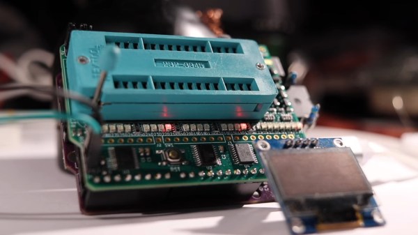
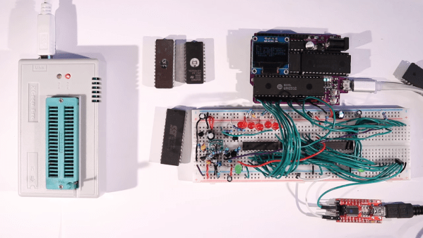
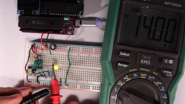
Switching Converter For EEPROM Programmer Taxes Solderless Breadboard

We all know that solderless breadboards have their limitations. All that stray capacitance can play hell with circuits, especially high-speed stuff, but they’re so darn useful that avoiding them in favor of some other prototyping method can be really hard. So we often just forge ahead, plugging in our parts and hoping for the best

A recent veteran of the breadboard battle is [Anders Nielsen], who kicked off a new project by prototyping this high-voltage boost converter on a breadboard, with mixed results. The project is a scratch-built programmer for old-school ROM chips, a task normally farmed out to a dedicated programmer, but where’s the sport in that? Besides, this is the future, and generating the 12 to 14 volts needed should be a snap. And it would be, except for the fact that his chosen chip, a MIC2288 switching boost regulator, is only available in an SMD package. Getting the chip and a few other SMD support components onto breadboard-compatible breakouts proved to be challenging, and getting it working once it was there was even more work.

A lot of the trouble was down to simple breadboarding errors, but the big problem was the input capacitance, which [Anders] had to fiddle with quite a bit to get the converter to 14 volts. The current maxes out at about 25 mA before the voltage starts dropping, which just might be enough to burn those old chips, so we’ll call this a provisional win and see what happens when he builds the rest of the programmer.

[Anders]’ experience here raises a good question: what’s the best way to prototype using fussy SMD components? PCBs are cheap enough that it’s tempting to go straight to one, but swapping parts in and out like he had to do here to get everything just right would be much harder that way. We’re not sure we know the answer, but we’re pretty sure we’ll hear your thoughts on that in the comments section.

Continue reading “Switching Converter For EEPROM Programmer Taxes Solderless Breadboard”

A Flasher Mac, 25 Years Later

Apple Macintosh computers of the 1990s came with a system ROM containing an Open Firmware implementation and the Mac Toolbox required to start the operating system. In many cases this was on a SIMM-like daughter board, and it would have been a true ROM that was unable to be reprogrammed. This is not the end of the story though, and [Doug Brown] set out on the trail of a Flash-based ROM module allowing the firmware on these machines to be updated.

The trail was warm thanks to an Apple developer utility found on a secondhand Mac prototype, allowing ROM flashing. A little disassembly allowed a list of valid IDs to be made, and this info coupled with a bit of reverse engineering from online photos of a real Apple Flash ROM from the ’90s allowed a new board to be created with four Am28F020  chips. He can now flash at will, with such oddities as running ROMs from different machines with the “wrong” startup chime. It’s an interesting little piece of 1990s Mac trivia, settled.

This isn’t the first time we’ve peered at Apple ROMs, indeed some of the older ones had plenty of Easter eggs hidden within.

Stuffing A 32-Pin Chip Into A 28-Pin Socket

What’s the difference between a 64k ROM in a 28-pin DIP and a 128k ROM in a 32-pin DIP? Aside from the obvious answers of “64k” and “four pins,” it turns out that these two chips have a lot in common, enough so that it only takes a little bodging to make them interchangeable — more or less.

For a variety of reasons revealed in the video below, [Anders Nielsen] use the SST39SF010, a Flash ROM in a 32-pin DIP, in place of the old standby W27C512, an EEPROM in a 28-pin DIP. To deal with those pesky extra pins on the Flash ROM, [Anders] dug into the data sheets and found that thanks to JEDEC standards, almost everything about the pinouts of the two chips is identical. The only real difference is the location of Vcc, plus the presence of a 16th address bus line on the more capacious Flash ROM.

Willing to sacrifice the upper half of the Flash chip’s capacity, [Anders] set about bodging the 32-pin chip to work in a 28-pin socket. The mods include a jumper from pin 32 to pin 30 on the Flash chip, which puts Vcc in the right place, and adding a couple of pull-up resistors for write-enable and A16. Easy enough changes, but unfortunately, [Anders] chose a Flash ROM with heavily oxidized pins, leading to some cold solder joints and intermittent problems while testing. There’s also the fact that not all boards have room for overhanging pins, a problem solved by adding a socket to create a little vertical clearance.

We found this to be a neat little hack, one that should make it a bit easier to use the wrong chip for the job. If you want to see where [Anders] is using these chips, check out his 6502 in an Arduino footprint or the bring-up of an old XT motherboard.

Continue reading “Stuffing A 32-Pin Chip Into A 28-Pin Socket”

HP1973 Project Highlights Workings Of HP-45 Calculator

[Sarah K Marr] dabbles in retrocomputing and has a fascination with the Hewlett Packard HP-45 calculator, the second calculator in HP’s series introduced in 1973. Over a year ago, she wrote an HP-45 emulator for use on a terminal, dubbed HP45TERM. Not content with success, she upped the challenge and decided to build an even better emulator with a full-featured GUI written in Python. Oh, and she made it multi-platform as well. The result is the HP1973 project.

[Sarah] thought it would take just a few days, but it grew into a much bigger project, as often happens. We’re glad it did because the results are fantastic. The emulator gives you access not only to the calculator itself but can see everything under the hood. The emulator provides full ROM visibility, hardware registers, and standard debugging operations like single stepping. ROM images are available for the HP-45, the HP-35, and the HP-80. The GUI display is configurable, and there’s a plethora of help and information explaining the calculator’s internals. Pre-built binaries are available for MacOS, Windows, and Python source code (3.10.10+) for all operating systems (you’ll need to `pip install numpy` first). The emulation is faithful to the original calculator, and even the hidden timer function can be accessed.

Check this out if you’re into retro calculators. Our own Al Williams wrote about the history of the HP-35 back in 2018 if you want to learn more. Thanks to [J Peterson] for sending in the tip.

Smooth Animations, Slick Bar Graphs, But No Custom Characters On This 16×2 OLED

Sometimes, finding new ways to use old hardware requires awesome feats of reverse engineering, software sleight of hand, and a healthy dose of good fortune. Other times, though, it’s just as simple as reading the data sheet and paying attention to details.

Not that we’re knocking [upir]’s accomplishment with these tricked-out 16×2 OLED displays. Far from it, in fact — the smoothly animated bar graph displays alphanumerics look fantastic. What’s cool about this is that he accomplished all this without resorting to custom characters. We’ve seen him use this approach before; this time around, the hack involves carefully shopping for a 16×2 OLED display with the right driver chip — a US2066 chip. You’ll still need a few tricks to get things working, like extra pull-up resistors to get the I2C display talking to an Arduino, plus a little luck that you got a display with the right character ROM.

Once all that is taken care of, getting the display to do what you want is mainly a matter of coding. In the video below, [upir] does a great job of walking through the finer points, and the results look great. The bar graphs in particular look fantastic, with silky-smooth animations.

Continue reading “Smooth Animations, Slick Bar Graphs, But No Custom Characters On This 16×2 OLED”

Creating A Game Boy ROM From Pictures

There are very few legal ways of obtaining ROM files for video games, and Nintendo’s lawyers are extremely keen on at least reminding you of the fact that you need to own the game cart before obtaining the ROM. With cart in hand, though, most will grab a cart reader to download the game files. While this is a tried-and-true method, for GameBoy games this extra piece of hardware isn’t strictly required. [Travis Goodspeed] is here to show us a method of obtaining ROM files from photographs of the game itself.

Bits can be manually edited to fix detection errors.

Of course, the chips inside the game cart will need to be decapped in order to obtain the pictures, and the pictures will need to be of high quality in order to grab the information. [Travis] is more than capable of this task in his home lab, but some work is still required after this step.

The individual bits in the Game Boy cartridges are created by metal vias on the chip, which are extremely small, but still visible under a microscope. He also has a CAD program that he developed to take this visual information and extract the data from it, which creates a ROM file that’s just as good as any obtained with a cart reader.

This might end up being slightly more work especially if you have to decap the chips and take the photographs yourself, but it’s nonetheless a clever way of obtaining ROM files due to this quirk of Game Boy technology. Encoding data into physical hardware like this is also an excellent way of ensuring that it doesn’t degrade over time. Here are some other methods for long-term data storage.

Pokemon ROM Hacks Brought To The Real World

If you were a kid anywhere in the last 30 years, it was nearly impossible to avoid at least some exposure to the Pokemon franchise. Whether that’s through games like Red and Blue to Scarlet and Violet, the brief summer everyone played Pokemon Go, or to other media such as the trading card game or anime, it seems to have transcended generations and cultures fairly thoroughly. And, if you’ve consumed all there is of official Pokemon video gaming, you may be surprised to know there are a number of slightly modified games floating around out there that can be translated onto game carts just like their official counterparts.

[imablisy] has played a lot of these ROM hack games but always within something like a virtual console or emulator, so he wanted something physical which would work on original hardware of the era. For this he’s making physical copies of Flora Sky and Vega, which are based on Pokemon Emerald and Fire Red originally for the Game Boy Advance. To get the cart he found a bunch of Mother 3 cartridges to use as the donor. From there he backed up his Emerald and Fire Red cartridges, modified the ROMs with the modifications, and then sent those new ROMs to overwrite the data on the Mother 3 cartridges.

A playable cartridge is only half of the build, though. He wants these to look and feel like real Pokemon games, so he added a color-appropriate translucent case and also printed custom holographic labels for each. It might seem straightforward, but from the style of [imablisy]’s video it’s clear he is very familiar with processes like these, from the artwork all the way to the hardware and software side. We’re also pleased no classic hardware was damaged during this build, much like this version of Doom on an NES cart which used a common game for the donor to upset the least number of collectors.

Continue reading “Pokemon ROM Hacks Brought To The Real World”