Stuffing A 32-Pin Chip Into A 28-Pin Socket

What’s the difference between a 64k ROM in a 28-pin DIP and a 128k ROM in a 32-pin DIP? Aside from the obvious answers of “64k” and “four pins,” it turns out that these two chips have a lot in common, enough so that it only takes a little bodging to make them interchangeable — more or less.

For a variety of reasons revealed in the video below, [Anders Nielsen] use the SST39SF010, a Flash ROM in a 32-pin DIP, in place of the old standby W27C512, an EEPROM in a 28-pin DIP. To deal with those pesky extra pins on the Flash ROM, [Anders] dug into the data sheets and found that thanks to JEDEC standards, almost everything about the pinouts of the two chips is identical. The only real difference is the location of Vcc, plus the presence of a 16th address bus line on the more capacious Flash ROM.

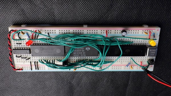
Willing to sacrifice the upper half of the Flash chip’s capacity, [Anders] set about bodging the 32-pin chip to work in a 28-pin socket. The mods include a jumper from pin 32 to pin 30 on the Flash chip, which puts Vcc in the right place, and adding a couple of pull-up resistors for write-enable and A16. Easy enough changes, but unfortunately, [Anders] chose a Flash ROM with heavily oxidized pins, leading to some cold solder joints and intermittent problems while testing. There’s also the fact that not all boards have room for overhanging pins, a problem solved by adding a socket to create a little vertical clearance.

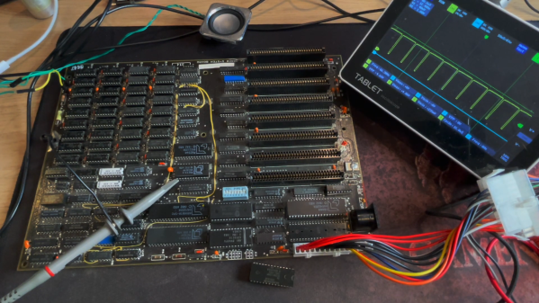
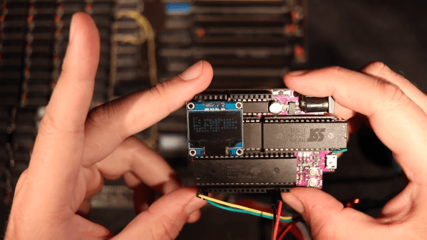
We found this to be a neat little hack, one that should make it a bit easier to use the wrong chip for the job. If you want to see where [Anders] is using these chips, check out his 6502 in an Arduino footprint or the bring-up of an old XT motherboard.

Continue reading “Stuffing A 32-Pin Chip Into A 28-Pin Socket”

HP1973 Project Highlights Workings Of HP-45 Calculator

[Sarah K Marr] dabbles in retrocomputing and has a fascination with the Hewlett Packard HP-45 calculator, the second calculator in HP’s series introduced in 1973. Over a year ago, she wrote an HP-45 emulator for use on a terminal, dubbed HP45TERM. Not content with success, she upped the challenge and decided to build an even better emulator with a full-featured GUI written in Python. Oh, and she made it multi-platform as well. The result is the HP1973 project.

[Sarah] thought it would take just a few days, but it grew into a much bigger project, as often happens. We’re glad it did because the results are fantastic. The emulator gives you access not only to the calculator itself but can see everything under the hood. The emulator provides full ROM visibility, hardware registers, and standard debugging operations like single stepping. ROM images are available for the HP-45, the HP-35, and the HP-80. The GUI display is configurable, and there’s a plethora of help and information explaining the calculator’s internals. Pre-built binaries are available for MacOS, Windows, and Python source code (3.10.10+) for all operating systems (you’ll need to `pip install numpy` first). The emulation is faithful to the original calculator, and even the hidden timer function can be accessed.

Check this out if you’re into retro calculators. Our own Al Williams wrote about the history of the HP-35 back in 2018 if you want to learn more. Thanks to [J Peterson] for sending in the tip.

Smooth Animations, Slick Bar Graphs, But No Custom Characters On This 16×2 OLED

Sometimes, finding new ways to use old hardware requires awesome feats of reverse engineering, software sleight of hand, and a healthy dose of good fortune. Other times, though, it’s just as simple as reading the data sheet and paying attention to details.

Not that we’re knocking [upir]’s accomplishment with these tricked-out 16×2 OLED displays. Far from it, in fact — the smoothly animated bar graph displays alphanumerics look fantastic. What’s cool about this is that he accomplished all this without resorting to custom characters. We’ve seen him use this approach before; this time around, the hack involves carefully shopping for a 16×2 OLED display with the right driver chip — a US2066 chip. You’ll still need a few tricks to get things working, like extra pull-up resistors to get the I2C display talking to an Arduino, plus a little luck that you got a display with the right character ROM.

Once all that is taken care of, getting the display to do what you want is mainly a matter of coding. In the video below, [upir] does a great job of walking through the finer points, and the results look great. The bar graphs in particular look fantastic, with silky-smooth animations.

Continue reading “Smooth Animations, Slick Bar Graphs, But No Custom Characters On This 16×2 OLED”

Creating A Game Boy ROM From Pictures

There are very few legal ways of obtaining ROM files for video games, and Nintendo’s lawyers are extremely keen on at least reminding you of the fact that you need to own the game cart before obtaining the ROM. With cart in hand, though, most will grab a cart reader to download the game files. While this is a tried-and-true method, for GameBoy games this extra piece of hardware isn’t strictly required. [Travis Goodspeed] is here to show us a method of obtaining ROM files from photographs of the game itself.

Bits can be manually edited to fix detection errors.

Of course, the chips inside the game cart will need to be decapped in order to obtain the pictures, and the pictures will need to be of high quality in order to grab the information. [Travis] is more than capable of this task in his home lab, but some work is still required after this step.

The individual bits in the Game Boy cartridges are created by metal vias on the chip, which are extremely small, but still visible under a microscope. He also has a CAD program that he developed to take this visual information and extract the data from it, which creates a ROM file that’s just as good as any obtained with a cart reader.

This might end up being slightly more work especially if you have to decap the chips and take the photographs yourself, but it’s nonetheless a clever way of obtaining ROM files due to this quirk of Game Boy technology. Encoding data into physical hardware like this is also an excellent way of ensuring that it doesn’t degrade over time. Here are some other methods for long-term data storage.

Pokemon ROM Hacks Brought To The Real World

If you were a kid anywhere in the last 30 years, it was nearly impossible to avoid at least some exposure to the Pokemon franchise. Whether that’s through games like Red and Blue to Scarlet and Violet, the brief summer everyone played Pokemon Go, or to other media such as the trading card game or anime, it seems to have transcended generations and cultures fairly thoroughly. And, if you’ve consumed all there is of official Pokemon video gaming, you may be surprised to know there are a number of slightly modified games floating around out there that can be translated onto game carts just like their official counterparts.

[imablisy] has played a lot of these ROM hack games but always within something like a virtual console or emulator, so he wanted something physical which would work on original hardware of the era. For this he’s making physical copies of Flora Sky and Vega, which are based on Pokemon Emerald and Fire Red originally for the Game Boy Advance. To get the cart he found a bunch of Mother 3 cartridges to use as the donor. From there he backed up his Emerald and Fire Red cartridges, modified the ROMs with the modifications, and then sent those new ROMs to overwrite the data on the Mother 3 cartridges.

A playable cartridge is only half of the build, though. He wants these to look and feel like real Pokemon games, so he added a color-appropriate translucent case and also printed custom holographic labels for each. It might seem straightforward, but from the style of [imablisy]’s video it’s clear he is very familiar with processes like these, from the artwork all the way to the hardware and software side. We’re also pleased no classic hardware was damaged during this build, much like this version of Doom on an NES cart which used a common game for the donor to upset the least number of collectors.

Continue reading “Pokemon ROM Hacks Brought To The Real World”

Squeezing A Minimalist 6502 Retrocomputer Onto A Single Breadboard

Over the years, and especially lately, we’ve seen tons of single-board retrocomputer builds. That’s fine with us — the more, the merrier. But they all start to run together a bit, with little to distinguish between them. Not so this about-as-compact-as-possible 6502 computer that fits on a single breadboard.

Now, when you do the math, it seems like there’s no way that [Anders Nielsen] would have been able to fit even a minimal chipset onto a standard solderless breadboard. The 40-pin 6502 alone takes up nearly two-thirds of the connections available; add in equally large but necessary chips like the 6522 interface adapter, ROM and RAM chips, and some support ICs, and one breadboard isn’t going to cut it. Luckily, some frugal engineers at MOS back in the 70s came up with the 6507, a variant on the 6502 in a 28-pin DIP. The other key to this build is the 6532 RAM-I/O-timer chip or RIOT, which puts a tiny amount of RAM and some IO lines on a single 40-pin DIP. Along with a 28-pin ROM, a 14-pin hex inverter, and a little crystal oscillator, the entire chipset just barely fits on a single breadboard.

But what can this minimalist 6502 actually do? As you can see in the video below, anything a 555 timer can do, and maybe a little bit more. That’s not a dig, of course — [Anders] actually calls out his initial blinkenlight application as a little more than a glorified 555, and actually comes up with a marginally more complex application just to prove the point. The interesting part here is dealing with the constraints imposed by the limited resources available on this machine.

We’re looking forward to whatever comes next for this clever build. It’s hard to see how some of the plans [Anders] has for it will still fit on a single breadboard, though — these things tend to spread out as they go.

Continue reading “Squeezing A Minimalist 6502 Retrocomputer Onto A Single Breadboard”

Bringing Up An Old Motherboard Is A Delicate Process

If you were around for the early days of the personal computer revolution, you’ll no doubt recall the excitement every time IBM announced a new version of its beige boxes. For a lot of us, the excitement was purely vicarious, for despite the “personal” moniker, mere mortals could rarely afford a branded IBM machine. But it was still cool to keep track of the latest releases, and dream of the days when cheap clones would make it possible to play.

[Anders Nielsen]’s recent find of an original IBM Model 5160 motherboard sort of echoes that long-ago excitement, but in a different way. This board, from a PC XT built in 1984, was in unknown condition upon arrival, so [Anders] set about a careful process to try to bring the board back to life. A quick visual inspection leaves one with a sense of both how much things have changed, and how much they’ve stayed the same. Aside from the big 40-pin DIP 8088 CPU and the BIOS ROMs, the board is almost completely populated with discrete logic chips, but at the same time, the basic footprint of a motherboard has changed very little.

The bring-up process in the video below includes checks of all the power rails for shorts, which ended up being a good call — drat those tantalums. After fixing that issue, [Anders] had a bit of trouble getting the board to POST, and eventually resorted to dumping the BIOS ROMs and inspecting the contents. One of the chips had picked up a case of the scramblies at some point, which was easy enough to fix thanks to images of the 5160 ROMs available online. We thought the trick of using a 64k ROM and just writing the BIOS image twice was pretty clever.

In the end, the board came up, although without video or keyboard — that’s for another day. Can’t find your own PC XT motherboard to play with? Then maybe you can just build one.

Continue reading “Bringing Up An Old Motherboard Is A Delicate Process”