[Brian Harms] made his living room window blinds open and close automatically using servos, an Arduino, and a SmartThings Arduino shield. Best of all, it’s connected to his Amazon Echo so that merely saying “Alexa, turn on/off the blinds” will open and close them.
To accomplish the feat [Brian] used two laser cut acrylic gears; one of which was attached to the servo horn, and the other to the long square rod running the length of the blinds. Despite using the bulky Arduino and shield, the finished product is inconspicuous and streamlined, and the single Arduino controls all three of the blinds in the living room. [Brian] answered a bunch of questions on a Reddit thread.
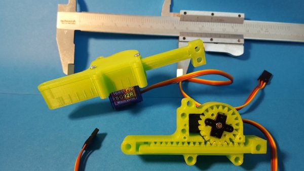
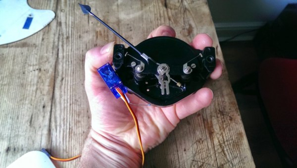
Micro servomotors are a hacker staple. You’ll find maybe four or five in an RC plane, while a hexbot build could soak up a dozen or more of the cheap and readily available devices. Unfortunately, long-throw linear actuators are a little harder to come by, so it’s nice to know you can 3D-print linear gearing for standard micro RC servos and roll your own.
Currently on revision 2, [Roger Rabbit]’s design is not just a quick and dirty solution. He’s really thought through the problems he observed with his first revision, and the result is a robust, powerful linear actuator. The pinion fits a trimmed servo crank arm, the mating rack is stout and stiff, and early backlash problems have been solved. The whole case is easy to assemble, and as the video below shows, the completed actuator can lift 300 grams.
We like [Roger]’s build process, especially the iterative approach to improving the design. We’ll stay tuned to see where it goes next – a continuous rotation servo for extra-long throws? While we wait, you might want to check out [Richard Baguley]’s recent primer on servos if you want a little background on the underlying mechanism.
How do you make things move? You add in a motor that converts electrical energy into motion. That’s a simple idea, but how do you know where the motor is? That’s where the servo motor comes in. By adding a sensor and a controller to the mechanism, these motors can figure out how far they have rotated and maintain that setting without any need for external control.
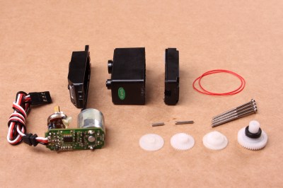
A disassembled servo motor showing the controller, motor, rotary encoder and gears. By oomlout, CC BY-SA 2.0
What is a Servo Motor?
These neat devices can be large or small, but they all share the same basic characteristics: a motor connected to a gearing mechanism and an encoder that detects the movement and speed of the motor. This combination means that the controlling device doesn’t need to know anything about the motor itself: the controller on the servo motor handles the process of feeding the appropriate power to the motor until it reaches the requested position. This makes it much easier to build things with servomotors, as the designer has already done all the hard work for you.
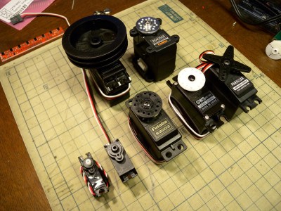
The first place that most people encounter a servo motor is in the small hobby servos that are used in remote control vehicles. Manufactured by companies like Hitec and Futaba, these drive a gear or arm that transfers the rotation of the motor to perform tasks like turning a wheel to steer a car, moving a control surface on an RC plane, or any task that requires a small range of motion at high precision. The gearing in the servomotor offers more torque than connecting the shaft directly to the motor. Most hobby servos of this type are restricted to a certain range of motion (usually 180 degrees) because the position encoder is a simple potentiometer connected to the output shaft.
A selection of different sized servo motors. By Osamu Iwasaki
Servomotors usually have three connection wires: a power line, a ground line and a signal line. The signal line is fed a pulse width modulation (PWM) signal that determines the angle that the servomotor moves to. As the name suggests, the length of the pulse (or the width, if you look at it on an oscilloscope) is the thing that controls the angle that the servo moves to: a short pulse (1 millisecond) sets it to the zero angle, while a long pulse of 2 milliseconds sets it to the maximum angle. A pulse length between these two limits signals the servomotor to move to the corresponding angle: 1.5 ms would set it to 90 degrees.
It is important to note that servomotors and stepper motors are not the same thing. Both are used for positioning, but steppers usually run without feedback. Instead, steppers turn (as the name suggest) in discrete steps. To figure out where a stepper motor is requires a limit switch, then driving the stepper until this is triggered. Then if you keep count out the number of steps that it’s traveled, you know where it is. That’s why devices like inkjet or 3D printers will move to their limits when they start up, so the controller can detect the far limit of the mechanism being driven, and calculate the current position from that.
How Do You Use A Servomotor?
Because the designers of servomotors have done most of the hard work for you, servomotors are very easy to use. To drive them, you just need to feed them power (usually 5V) and feed the PWM signal to the servomotor. You can drive them directly from an Arduino or similar microcontroller using a library that converts an angle into a PWM signal on one of the output pins.
Each servomotor requires a dedicated output pin if they are being driven this way, though, so if you are driving a lot of servomotors, a dedicated controller makes more sense. Devices such as the Adafruit Servo Shield and the Pololu Maestro allow you to control multiple servos from a single output pin on the microcontroller: the microcontroller sends a signal to the device addressing each servo in turn, and the device converts this into the PWM signals for each. If you need to drive a lot of servos, the SD84 can control up to 84 servos at once from a single USB port.
Typewriters with voice recognition have existed for over one hundred years; they were called secretaries. Robots are taking all the jobs now, and finally dictation and typing is a job that can be handled by a computer. [Zip Zaps] used an old Smith Corona typewriter to automate the process of turning dictation into print. Like a secretary hunched over an anachronistic IBM Selectric in the first season of Mad Men, this robot will take dictation and accept the overt sexism of a 1960s Manhattan ad agency.
Instead of the machinations of a few biological actuators, this typewriter is controlled with an array of servos driven by Pololu Maestro servo controller. There are twelve servos that move a small actuator down onto the keys, and another twelve servos that move the others above the correct row of the keyboard. The carriage return lever is actuated by a stepper motor, linear rail, and giant plastic lever.
While a robot that can use a typewriter is impressive, the real trick is getting it to take dictation. [Zip Zaps] used the built-in voice recognition found in Windows for this, streaming characters over a serial port to the Arduino-based electronics.
Does it work? Yes, surprisingly it does. Is it useful? Well, typewriters naturally have a cleaner, more analog tone about them, and you can’t replicate the typing experience of an old Smith Corona typewriter with a digital format. This build is just the natural extension of what digital electronics are capable of these days, and we look forward to seeing someone with this amazing device in our local Starbucks.
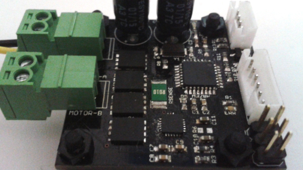
Brushless DC motors, and their associated drive electronics, tend to be expensive and complicated. [Ottoragam] was looking for a cheaper alternative and built this Brushed DC motor servo controller and the results look pretty promising. Check out the video after the break.
He needed a low cost, closed loop drive for his home-brew CNC. The servo drive is able to supply a brushed DC motor with up to 7 A continuous current at up to 36 V which works out to about 250 W or 1/3 HP. It does closed loop control with feedback from a quadrature encoder. The drive accepts simple STEP and DIRECTION signals making it easy to interface with micro controllers and use it as a replacement for stepper motors in positioning applications. All of the control is handled by an ATmega328P. It takes the input signals and encoder data, does PID control, and drives the motor via the DRV8701 full bridge MOSFET driver. There’s also some error detection for motor over-current and driver under-voltage. Four IRFH7545 MOSFETs in H-bridge configuration form the output power stage.
This is still work in progress, and [Ottoragam] has a few features pending in his wish list. The important ones include adding a serial interface to make it easy to adjust the PID parameters and creating a GUI to make the adjustment easier. The project is Open Source and all source files available at his Github repository. The board is mostly surface mount, but the passives are all 0805, so it ought to be easy to assemble. The QFN footprint for the micro controller could be the only tricky one. [Ottoragam] would love to have some beta testers for his boards, and maybe some helpful comments to improve his design.
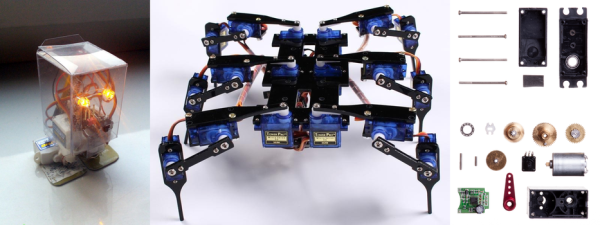
The ESP8266 is finding its way into all sorts of projects these days. It’s a capable little device, to be sure, but we’d have to say that finding it running a quadruped robot that can hop and run was a little unexpected. And to have it show up in such an adorable design was pretty cool too.
From the looks of [Javier Isabel]’s build log, he put a lot of thought into [Kame]. All the body parts and linkages are 3D printed from PLA, with the nice touch of adding a contrasting color. The legs are powered by eight high-speed Turnigy servos, and good quality bearings are used in the linkages. A NodeMCU runs the show with custom oscillator algorithms that control the various gaits, including the hopping motion. The BOM even lists “Adhesive 12mm diameter eyes” – perhaps that’s some sort of slang for the more technically correct “googly eyes.”
Built primarily as a test platform for studying different gaits, there doesn’t seem to be much in the way of sensors in [Kame]’s current incarnation. But with an ESP8266 under the hood, the possibilities for autonomous operation are good. We look forward to seeing where this project goes next. And we kid about the cuteness factor, but never doubt the power of an attractive design to get the creative juices flowing.
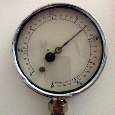
When your passion is a sport that depends on Mother Nature’s cooperation, you need to keep a close eye on weather conditions. With this in mind, and not one to let work distract him from an opportunity to play, [mechanicalsquid] decided to build a wind-monitoring gauge with an old-school look to let him know when the wind is right for kitesurfing.
Being an aficionado of big engineering helped [mechanicalsquid] come up with a style for his gauge – big old dials and meters. We hesitate to apply the “steampunk” label to every project that retasks old technology, but it sure looks like a couple of the gauges he used could have been for steam, so the moniker probably fits here. Weather data for favorite kitesurfing and windsurfing locales is scraped from the web and applied to the gauges to indicates wind speed and direction. [mechanicalsquid] made a valiant effort to drive the voltmeter coil directly from the Raspberry Pi, but it was not to be. Servos proved inaccurate, so steppers do the job of moving the needles on both gauges. Check out the nicely detailed build log for this one, too.


 Being an aficionado of big engineering helped [mechanicalsquid] come up with a style for his gauge – big old dials and meters. We hesitate to apply the “steampunk” label to every project that retasks old technology, but it sure looks like a couple of the gauges he used could have been for steam, so the moniker probably fits here. Weather data for favorite kitesurfing and windsurfing locales is scraped from the web and applied to the gauges to indicates wind speed and direction. [mechanicalsquid] made a valiant effort to drive the voltmeter coil directly from the Raspberry Pi, but it was not to be. Servos proved inaccurate, so steppers do the job of moving the needles on both gauges. Check out the nicely detailed build log for this one, too.


