When attempting to secure something, whether it’s a computer, sensitive data, or valuables, there’s always going to be a way to break that security. It might be impossibly hard, like taking centuries to brute-force an encryption algorithm, but it’s weakness is still there. And, like the future might make certain encryption obsolete, modern electronics has made security of the past somewhat obsolete as well. [Startup Chuck] has been using tools the creators of safes from the late 1800s could probably not have imagined.
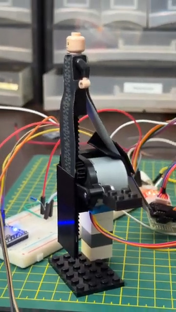
The tool that [Startup Chuck] has come up with is known as an autodialer in the safe-cracking world, and as its name suggests it automates the process of opening the safe by trying as many combinations as possible. The autodialer attaches to the safe with three magnetic feet and couples to the dial through a chuck attached to a magnetic clutch, which allows the autodialer to disengage as soon as the correct combination is found. It’s driven with a stepper motor which can test out combinations so fast that [Startup Chuck] needed to take 240 fps video and slow it down to make sure that the mechanism was behaving properly.
The autodialer itself can’t actually open the safe, though. The last step of the process is taken care of by a bungie cord, attached to the safe handle to pre-tension it enough so that when the correct combination is finally entered the safe pops open automatically. For anyone looking to duplicate the project, [Startup Chuck] has added the program code to a GitHub page. If you’re looking at a more modern safe, though, there are of course ways to crack their security systems as well.
Continue reading “Automatically Crack Safes With This Autodialer”