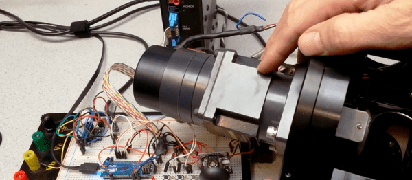
When you already know exactly where and how you’d like your motor to behave, a code-compile-flash-run-debug cycle can work just fine. But if you want to play around with a stepper motor, there’s nothing like a live interface. [BrendaEM]’s RDL is a generic stepper motor driver environment that you can flash into an Arduino. RDL talks to your computer or cell phone over serial, and can command a stepper-driver IC to move the motor in three modes: rotary, divisions of a circle, and linear. (Hence the acronumical name.) Best of all, the entire system is interactive. Have a peek at the video below.
The software has quite a range of capabilities. Typing “?” gets you a list of commands, typing “@” tells you where the motor thinks it is, and “h” moves the motor back to its home position. Rotating by turns, degrees, or to a particular position are simple. It can also read from an analog joystick, which will control the rotation speed forward and backward in real time.
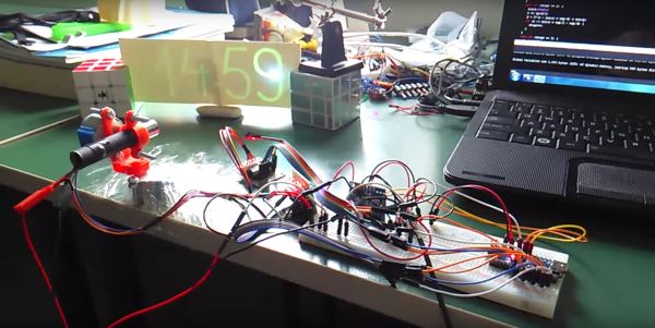
Division mode carves the pie up into a number of slices, and the motor spins to these particular locations. Twelve, or sixty, divisions gives you a clock, for instance. Acceleration and deceleration profiles are built in, but tweakable. You can change microstepping on the fly, and tweak many parameters of the drive, and then save all of the results to EEPROM. If you’re playing around with a new motor, and don’t know how quickly it can accelerate, or what speeds it’s capable of, nothing beats playing around with it interactively.
Continue reading “A Command-Line Stepper Library With All The Frills”

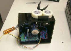 The first thing the team had to do was to mount the scissors so they would cut reliably. One of the stepper motors was attached to a drive wheel that had a bolt mounted on it. This went through one of the scissors’ handles, the other handle was held in place on the machine using screws. The second stepper motor was used to rotate the wheels that drives the cable through to the correct length. [2PrintBeta] used a