One way to understand how the 555 timer works and how to use it is by learning what the pins mean and what to connect to them. A far more enjoyable, and arguably a more useful way to learn is by looking at what’s going on inside during each of its modes of operation. [Dejan Nedelkovski] has put together just such a video where he walks through how the 555 timer IC works from the inside.
We especially like how he immediately removes the fear factor by first showing a schematic with all the individual components but then grouping them into what they make up: two comparators, a voltage divider, a flip-flop, a discharge transistor, and an output stage. Having lifted the internals to a higher level, he then walks through examples, with external components attached, for each of the three operating modes: bistable, monostable and astable. If you’re already familiar with the 555 then you’ll enjoy the trip down memory lane. If you’re not familiar with it, then you soon will be. Check out his video below.
As with the age-old panic after realizing you have left an oven on, a candle lit, and so on, a soldering tool left on is a potentially serious hazard. Hackaday.io user [Nick Sayer] had gotten used to his Hakko soldering iron’s auto shut-off and missed that feature on his de-soldering gun of the same make. So, what was he to do but nip that problem in the bud?
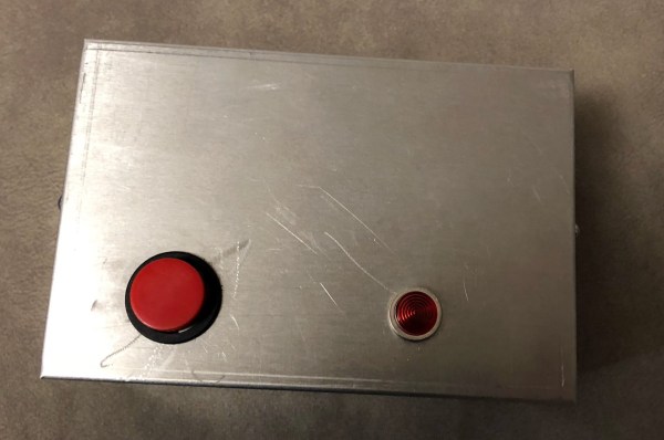
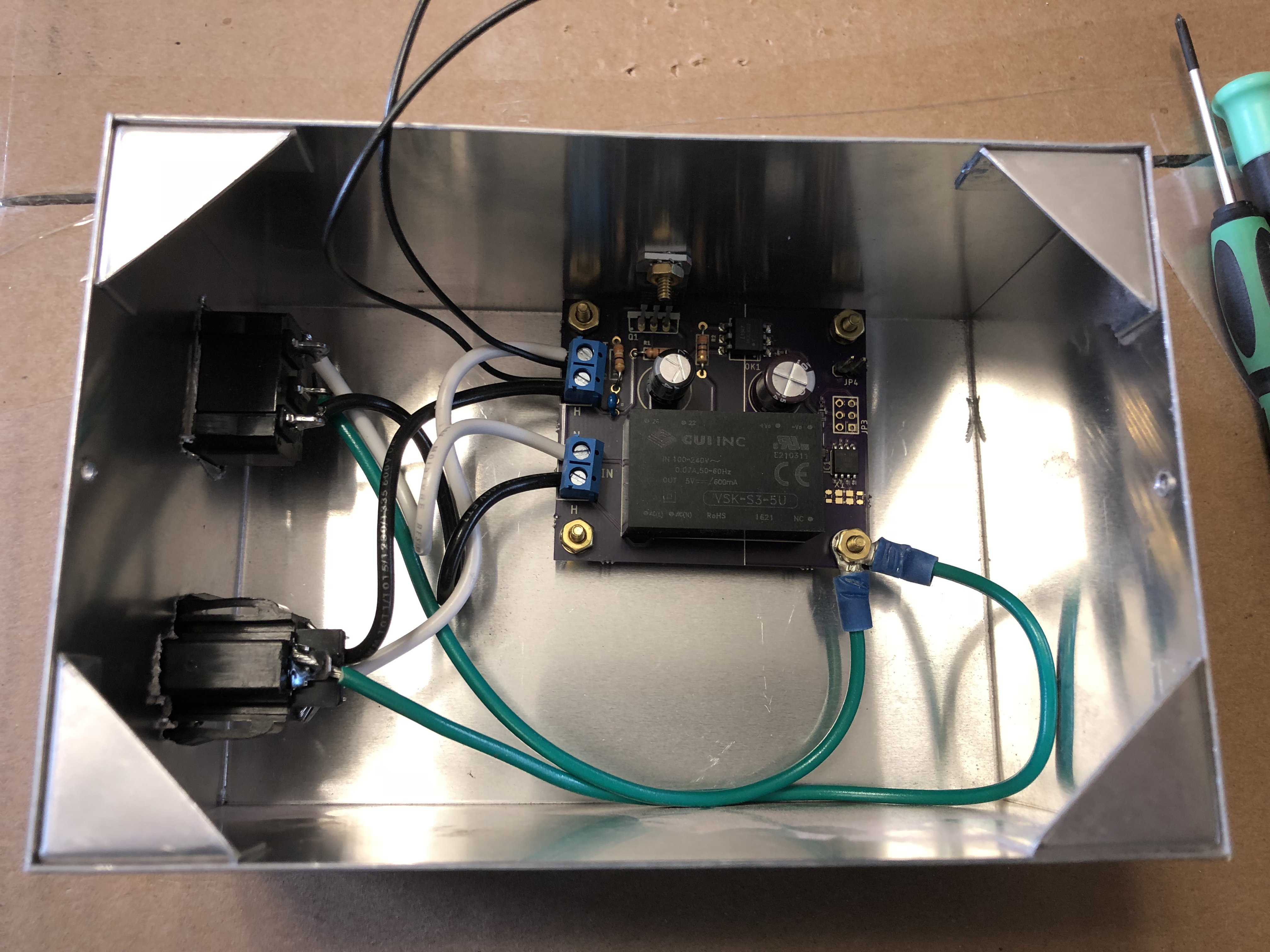
Instead of modding the tool itself, he built an AC plug that will shut itself off after a half hour. Inside a metal project box — grounded, of course — an ATtiny85 is connected to a button, an opto-isolated TRIAC AC power switch, and a ‘pilot’ light indicating power. After a half hour, the ATtiny triggers the opto-isolator and turns off the outlet, so [Sayer] must push the button if he wants to keep working. He notes you can quickly double-tap the button for a simple timer reset.
Sometimes the most satisfying hacks are those that spring from a situation where resources are limited, either by choice or by chance. Constraints tend to stir the creative juices.
Serial Hackaday poster [limpkin] limited himself to a one-day build with what he had on hand for this bus-route countdown timer. Full points for actually building something useful, and extra credit for making something to keep his wife from being late for work.
The principle is simple: scrape a web page to find out how much time is left before either of two busses leaves his wife’s stop, and display the number of minutes left on a huge LED display. The parts bin gave up everything needed, including an ESP8266, a boost converter, a charge controller, and the display and driver. We’re skeptical that the PCB was fabricated the same day; looks like [limpkin] is only counting the design and coding time in his 10-hour build. Still, it’s a testament to what’s possible with a deep inventory and the skills to put it to use.
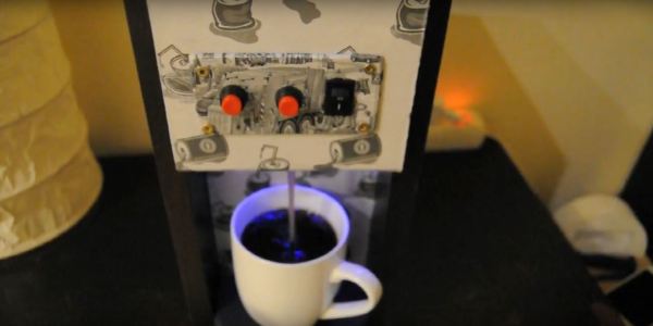
[truebassB]’s dispenser operates around a 555 timer, adjusted by a potentiometer. Push a button and a cup pours in a few seconds, or hold the other button to dispense as much as you want.
The dispenser is made from MDF and particle board glued together, with some LEDs and paper prints to spruce it up. Just don’t forget a small spill sink for any miscalculated pours. You needn’t fret over the internals either, as the parts are easily acquired: a pair of momentary switches, a 12V micro air pump, a brass nozzle, food-safe pvc tube, a custom 555 timing circuit — otherwise readily available online — a toggle switch, a power supply plug plus adapter and a 12V battery.
We can race against the clock when assembling jigsaw puzzles online but what about competing against each other in the real world? [HomeMadeGarbage] came up with the simplest of solutions with his jigsaw puzzle timer that stops only when the puzzle’s completely assembled.
Copper strip on back of puzzle
His simple solution was to attach copper foil tape to the back of the pieces, with overlap. He did this in a serpentine pattern to ensure that all pieces had a strip of the tape. The puzzle he used comes with a special container to assemble it in. At two corners of that container, he put two more pieces of copper foil, to which he soldered wires. Those two act as a switch. Only when the puzzle is completed will those two pieces be connected through the serpentine strip on the back of the puzzle.
Next, he needed a timer. The two wires from the puzzle container go to an Arduino UNO which uses an ILI9325 touch panel TFT display for both the start, stop, and reset buttons, and to show the time elapsed. Press the touch screen when it says START and begin assembling the puzzle. When the last piece is inserted, the serpentine strip of copper tape completes the circuit and only then does the Arduino program stop the timer. As you can see from the video below, the result makes doing the puzzle lots of fun.
I am a crappy software coder when it comes down to it. I didn’t pay attention when everything went object oriented and my roots were always assembly language and Real Time Operating Systems (RTOS) anyways.
So it only natural that I would reach for a true In-Circuit-Emulator (ICE) to finish of my little OBDII bus to speed pulse generator widget. ICE is a hardware device used to debug embedded systems. It communicates with the microcontroller on your board, allowing you to view what is going on by pausing execution and inspecting or changing values in the hardware registers. If you want to be great at embedded development you need to be great at using in-circuit emulation.
Not only do I get to watch my mistakes in near real time, I get to make a video about it.
Getting Data Out of a Vehicle
I’ve been working on a small board which will plug into my car and give direct access to speed reported on the Controller Area Network (CAN bus).
To back up a bit, my last video post was about my inane desire to make a small assembly that could plug into the OBDII port on my truck and create a series of pulses representing the speed of the vehicle for my GPS to function much more accurately. While there was a wire buried deep in the multiple bundles of wires connected to the vehicle’s Engine Control Module, I have decided for numerous reasons to create my own signal source.
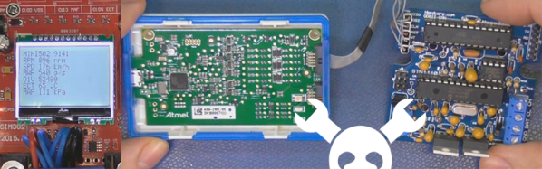
At the heart of my project is the need to convert the OBDII port and the underlying CAN protocol to a simple variable representing the speed, and to then covert that value to a pulse stream where the frequency varied based on speed. The OBDII/CAN Protocol is handled by the STN1110 chip and converted to ASCII, and I am using an ATmega328 like found on a multitude of Arduino’ish boards for the ASCII to pulse conversion. I’m using hardware interrupts to control the signal output for rock-solid, jitter-free timing.
Walk through the process of using an In-Circuit Emulator in the video below, and join me after the break for a few more details on the process.
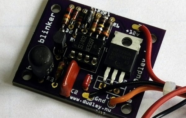
Sometimes you use a Raspberry Pi when you really could have gotten by with an Arudino. Sometimes you use an Arduino when maybe an ATtiny45 would have been better. And sometimes, like [Bill]’s motorcycle tail light project, you use exactly the right tool for the job: a 555 timer.
One of the keys of motorcycle safety is visibility. People are often looking for other cars and often “miss” seeing motorcyclists for this reason. Headlight and tail light modulators (circuits that flash your lights continuously) are popular for this reason. Bill decided to roll out his own rather than buy a pre-made tail light flasher so he grabbed a trusty 555 timer and started soldering. His circuit flashes the tail light a specific number of times and then leaves it on (as long as one of the brake levers is depressed) which will definitely help alert other drivers to his presence.
[Bill] mentions that he likes the 555 timer because it’s simple and bulletproof, which is exactly what you’d need on something that will be attached to a motorcycle a be responsible for alerting drivers before they slam into you from behind.
We’d tend to agree with this assessment of the 555; we’ve featured entire 555 circuit contests before. His project also has all of the tools you’ll need to build your own, including the files to have your own PCB made. If you’d like inspiration for ways to improve motorcycle safety in other ways, though, we can suggest a pretty good starting point as well.