Hackaday Links Column Banner

Hackaday Links: The Last One Of 2014

The guy behind the Microslice, a tiny Arduino-controlled laser cutter, has a new Kickstarter out. It’s called the Multibox PC, and it’s exactly what you need if you want to turn a Raspi, Banana Pi, HummingBoard, or Odroid U3 into an all-in-one desktop. 14″ 1366 x 768 LCD, and speakers turns dev boards into a respectable little Linux box.

If you’re learning to design schematics and lay out PCBs, you should really, really think about using KiCAD. It’s the future. However, Eagle is still popular and has many more tutorials. Here’s another. [Mushfiq] put together a series of tutorials for creating a library, designing a schematic, and doing the layout.

Another kickstarter wristwatch. But wait, this thing has a circular display. That’s really cool. It’s a 1.4″ 220×220 pixel, 262k color display. No, the display doesn’t use a polar coordinate system.

[Jari] wrote a digital logic simulator, Atanua, started selling licenses, and figured out it wasn’t worth developing on his own anymore. As promised, Atanua is now open source. If you want to look at the finances behind Atanua, here you go.

In 1970, you didn’t have a lot of options when it came to memory. One of the best options was Intel’s 1405 shift register – 512 bits of storage. Yes, shift registers as memory. [Ken Shirriff] got his hands on a memory board from a Datapoint 2200 terminal. Each of the display boards had 32 of these shift registers. Here’s what they look like on the inside

There’s a lot of talk about North Korean hackers, and a quick review of the yearly WordPress stats for Hackaday puts a tear in our eye. This year, there were fifty-four views from the Democratic People’s Republic of Korea. That’s just great. It’s awesome to see the hacker ethos make it to far-flung lands and through highly restricted firewalls. There’s still a long road ahead of us, though, and we’ll redouble our efforts on bringing the hacker mindset to Tuvalu and Saint Helena in the year 2015.

unicycle

Offset Unicycle Built Mostly From A Single Bicycle

[Lou’s] friends all said that it would be impossible to build a unicycle that had offset pedals. Moving the pedals to the front of the unicycle would throw off the balance and prevent the user from being able to ride it. [Lou] proved them wrong using mostly components from a single donor bicycle.

The donor bike gets chopped up into a much smaller version of itself. The pedals stay attached in the original location and end up being out in front of the rider. The seat is moved backwards, which is the key to this build. Having the rider’s legs out in front requires that there be a counter balance in back. Moving the seat backwards gets the job done with relative ease.

To prevent the hub from free wheeling, [Lou] lashes the sprocket directly to the wheel spokes using some baling wire. He also had to remove the derailer and shorted the chain. All of this gives the pedals a direct connection to the wheel, allowing for more control. The video does a great job explaining the build quickly and efficiently. It makes it look easy enough for anyone to try. Of course, actually riding the unicycle is a different matter. Continue reading “Offset Unicycle Built Mostly From A Single Bicycle”

DIY Optoisolator

MacGyvered Optoisolator Is A Great Introduction

Sometimes the best way to learn about a technology is to just build something yourself. That’s what [Dan] did with his DIY optoisolator. The purpose of an optoisolator is to allow two electrical systems to communicate with each other without being electrically connected. Many times this is done to prevent noise from one circuit from bleeding over into another.

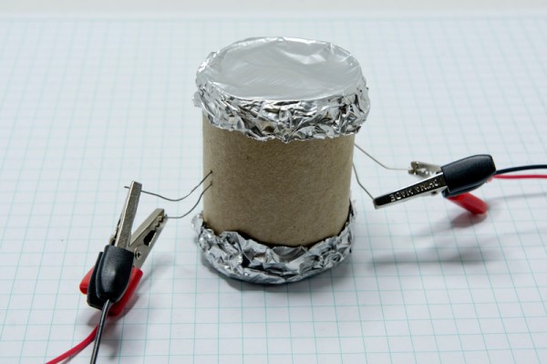
[Dan] built his incredibly simple optoisolator using just a toilet paper tube, some aluminum foil, an LED, and a photo cell. The electrical components are mounted inside of the tube and the ends of the tube are sealed with foil. That’s all there is to it. To test the circuit, he configured an Arduino to send PWM signals to the LED inside the tube at various pulse widths. He then measured the resistance on the other side and graphed the resulting data. The result is a curve that shows the LED affects the sensor pretty drastically at first, but then gets less and less effective as the frequency of the signal increases.

[Dan] then had some more fun with his project by testing it on a simple temperature controller circuit. An Arduino reads a temperature sensor and if the temperature rises above a certain value, it turns on a fan to cool the sensor off again. [Dan] first graphed the sensor data with no fan hooked up. He only used ambient air to cool things down. The resulting graph is a pretty smooth curve. Next he hooked the fan up and tried again. This time the graph went all kinds of crazy. Every time the fan turned on, it created a bunch of electrical noise that prevented the Arduino from getting an accurate analog reading of the temperature sensor.

The third test was to remove the motor circuit and move it to its own bread board. The only thing connecting the Arduino circuit to the fan was a wire for the PWM signal and also a common ground. This smoothed out the graph but it was still a bit… lumpy. The final test was to isolate the fan circuit from the temperature sensor and see if it helped the situation. [Dan] hooked up his optoisolator and tried again. This time the graph was nice and smooth, just like the original graph.

While this technology is certainly not new or exciting, it’s always great to see someone learning by doing. What’s more is [Dan] has made all of his schematics and code readily available so others can try the same experiment and learn it for themselves.

Hackaday logo with the words "4-Minutes to Entry"

4-Minutes To Entry

If you think it’s too much work to write about your projects you’re simply wrong, and I’m going to prove it to you.

The first of this set of videos walks though the steps for submitting an official entry… I did it in under 4 minutes.  The second clip covers the extra details you need to post to meet the requirements for the first cutoff on August 20th.

This is the bare minimum needed for your project to be reviewed by the judging panel. But here’s the thing: get your basics down early, then refine as you go along. The Hackaday Prize celebrates the journey of developing interested connected devices. From now until November you should be working on the build and adding to infor to your project post as you go.

Did we mention your odds of winning this thing are really good?

Automatic Audio Leveling Circuit Makes Scanning More Fun

alan-scope1

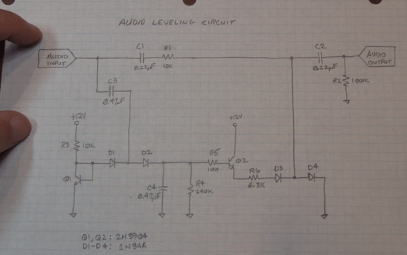
[Alan’s] friend came to him with a problem. He loved listening to his scanner, but hated the volume differences between stations. Some transmitters would be very low volume, others would nearly blow his speakers. To solve the problem, [Alan] built up a quick automatic leveling circuit (YouTube link) from parts he had around the lab.

[Alan’s] calan-scope2ircuit isn’t new, he states right in the video that various audio limiting, compressing, and automatic gain control circuits have been passed around the internet for years. What he’s brought to the table is his usual flair for explaining the circuits’ operation, with plenty of examples using the oscilloscope. (For those that don’t know, when [Alan] isn’t building circuits for fun, he’s an RF applications engineer at Tektronix).

Alan’s circuit is essentially an attenuator. It takes speaker level audio in (exactly what you’d have in a desktop scanner) and outputs a limited signal at about 50mv peak to peak, which is enough to drive an auxiliary amplifier. The attenuator is made up of a resistor and a pair of 1N34A Germanium diodes. The more bias current applied to the diodes, the more they will attenuate the main audio signal. The diode bias current is created by a transistor-based peak detector circuit driven off the main audio signal.
But don’t just take our word for it, watch the video after the break.

Continue reading “Automatic Audio Leveling Circuit Makes Scanning More Fun”

CPLD Tutorial: Learn Programmable Logic The Easy Way

The guys over at hackshed have been busy. [Carl] is making programmable logic design easy with an 8 part CPLD tutorial. (March 2018: Link dead.  Try the Wayback Machine.) Programmable logic devices are one of the most versatile hardware building blocks available to hackers. They also can have a steep learning curve. Cheap Field Programmable Gate Arrays (FPGA) are plentiful, but can have intricate power requirements. Most modern programmable logic designs are created in a Hardware Description Language (HDL) such as VHDL or Verilog. Now you’ve got a new type of device, a new language, an entirely new programming paradigm, and a complex IDE to learn all at once. It’s no wonder FPGAs have sent more than one beginner running for the hills.

The tutorial cuts the learning curve down in several ways. [Carl] is using Complex Programmable Logic Devices (CPLD). At the 40,000 foot level, CPLDs and FPGAs do the same thing – they act as re-configurable logic. FPGAs generally do not store their configuration – it has to be loaded from an external FLASH, EEPROM, or connected processor. CPLDs do store their configuration, so they’re ready as soon as they power up. As a general rule, FPGAs contain more configurable logic than CPLDs. This allows for larger designs to be instantiated with FPGAs. Don’t knock CPLDs though. CPLDs have plenty of room for big designs, like generating VGA signals.

[Carl] also is designing with schematic capture in his tutorial. With the schematic capture method, digital logic schematics are drawn just as they would be in Eagle or KiCad. This is generally considered an “old school” method of design capture. A few lines of VHDL or Verilog code can replace some rather complex schematics. [Carl’s] simple designs don’t need that sort of power though. Going the schematic capture route eliminates the need to learn VHDL or Verilog.

[Carl’s] tutorial starts with installing Altera’s Quartus II software. He then takes the student through the “hardware hello world” – blinking an LED.  By the time the tutorial is done, the user will learn how to create a 4 bit adder and a 4 bit subtractor. With all that under your belt, you’re ready to jump into big designs – like building a retrocomputer.

[Image via Wikimedia Commons]

3D Printering: Making A Thing With Solidworks, Part II

printering1

Last week we started to Make a Thing  in Solidworks.  We got as far as sketching and extruding the base. This week we’ll make the back portion. We’ll use some of the same techniques in Part I and a few new features such as 3D filleting and the Hole Wizard.

As you know, this is not the first ‘Making a Thing’ tutorial. In case you missed them, the softwares previously covered in the 3D Printering series are:

engineeringdrawingblack1

Continue reading “3D Printering: Making A Thing With Solidworks, Part II”