In the United States in 1939, television sets still had a long way to go before they pretty much sold themselves. Efforts to do just that are what led to RCA’s Lucite Phantom Telereceiver, which aimed to show people a new way to receive broadcast media.
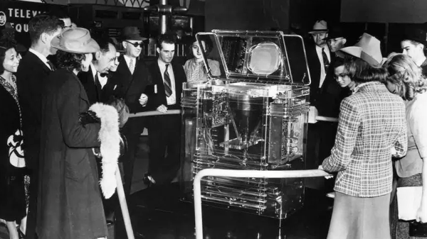
 Created for the 1939 World’s Fair, the TRK-12 Lucite Phantom Telereceiver introduced people to the concept of television. Production models were housed in contemporary wood cabinets, but the clear acrylic (itself also a relatively new thing) units allowed curious potential customers to gaze within, and see what was inside these devices.
One interesting feature is the vertically-mounted cathode ray tube, which reflects off a mirror in the top cover of the cabinet for viewing. This meant that much of the bulk of the TRK-12 could be vertical instead of horizontal. Important, because the TRK-12 was just over a meter tall and weighed 91 kilograms (or just over 200 lbs.)
Clearly a luxury item, the TRK-12 sold for $600 which was an eye-watering sum for the time. But it was a glimpse of the future, and as usual, the future is made available a few ticks early to those who can afford the cost.
Want to see one in person? You might be in luck, because an original resides at the MZTV Museum of Television in Toronto, Canada.