Plugging in something like an antique radio to see if it works is a good way to have a bad time, because some old components don’t age well. For vintage electronics, inspection and repair are steps one and two. When it comes time to cautiously apply power, it’s best to use what’s called a dim-bulb tester and most hackers can probably put one together from scrap.
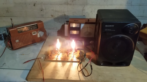
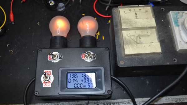
These testers make it easier, and safer, to tell if there are any big problems with a device’s power supply. In its simplest form, a dim-bulb tester puts an incandescent lamp in series between a device — like an old radio — and the AC power from a wall socket. Thanks to this, if the device has a short circuit, the bulb will simply light up instead of causing any damage.
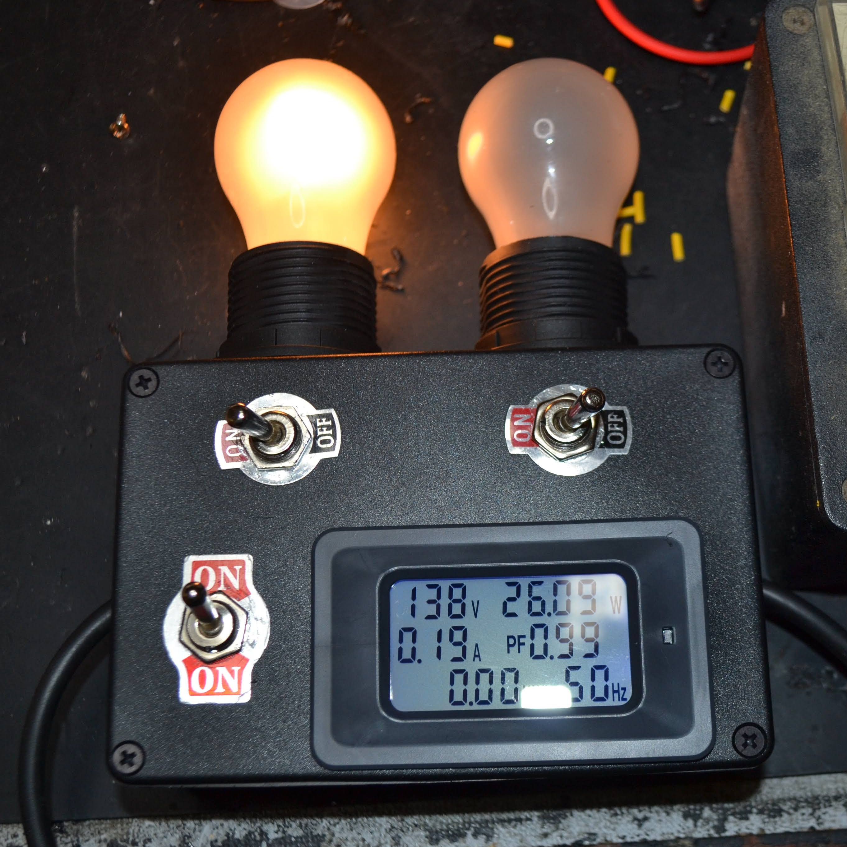
Ideally, one uses a bulb with a wattage rating that is roughly equal to the power consumption of the device being tested. If all is well, the bulb will glow very faintly and the device will work normally. A brightly glowing bulb would indicate excessive current draw. To allow some flexibility, [Doz]’s tester design allows using one or two 60 W incandescent bulbs in series, and even incorporates an inexpensive power monitor.
A dim-bulb tester isn’t an in-depth diagnostic tool but it is effective, simple, and allows for a safe startup even if there’s a serious problem like a short. It helps protect valuable hardware from going up in smoke. In fact, the fundamental concept of limiting power to protect hardware in case of a fault has also been applied in the world of retrocomputing, where it helps protect otherwise irreplaceable hardware if something goes wrong.