AlienFX

Simple Terminal Hack Is Fit For Hollywood

We’ve all seen the cheesy hacker scenes in movies and on TV. Three dimensional file system browsers, computer chip cityscapes, and other ridiculous visualizations to make the dull act of sitting at a keyboard look pretty on the silver screen. While real hackers know those things are often silly and impractical, sometimes we do go out of our way to pretty things up a bit.

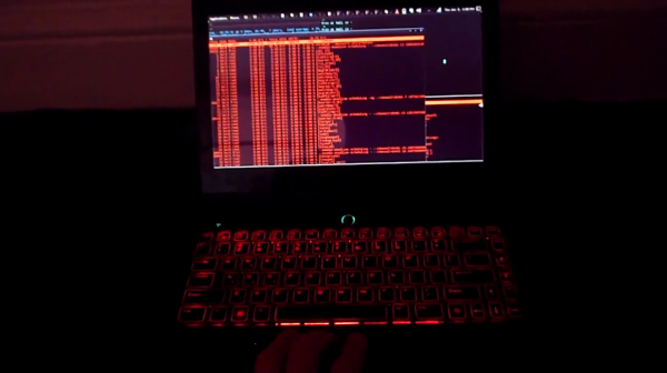
Hollywood might be able to learn a thing or two from this latest hack. [Yuri] modified his Linux terminal to change the color of the back lights on his laptop’s keyboard. It’s the kind of thing that actually would look good in a modern hacker movie, and [Yuri] is living proof that it’s something that a real-life hacker would actually use!

[Yuri] has been running Simple Terminal. The Simple Terminal project aims to build a replacement for the default xterm program that removes all of the unnecessary features and simplifies the source code. It also aims to make your terminal experience prettier. Part of making things prettier means that you can choose the font color for your terminals, and of course each terminal window can have its own color if you so choose.

[Yuri] happens to own an Alienware laptop. This laptop comes with RGB LEDs behind the keyboard, allowing you to light them up just about any color you could ever want. [Yuri] thought it would be cool if his keyboard color matched the font color of his terminal windows. Thanks to AlienFX, he was able to write a simple patch for Simple Terminal that does exactly this. Now whenever he selects a terminal window, the keyboard automatically switches colors to match the text in that window. Be sure to check out the video below. Continue reading “Simple Terminal Hack Is Fit For Hollywood”

Open Sourcing Satellite Telemetry

Launched in 1978, the International Sun/Earth Explorer 3 was sent on a mission to explore the Earth’s interaction with the sun. Several years later, the spacecraft changed its name to the International Cometary Explorer, sent off to explore orbiting ice balls, and return to Earth earlier this year. Talking to that spacecraft was a huge undertaking, with crowdfunding campaigns, excursions to Arecibo, and mountains of work from a team spanning the globe. Commanding the thrusters onboard the satellite didn’t work – there was no pressure in the tanks – but still the ICE mission continues, and one of the lead radio gurus on the team has put up the telemetry parser/display crafted for the reboot project up on Github.

The guy behind the backend for the ICE/ISEE reboot project should be well-known to Hackaday readers. He’s the guy who came up with a Software Defined Radio source block for a cheap USB TV tuner, waking everyone up to the SDR game. He’s also played air traffic controller by sitting out near an airport with a laptop, and has given talks at Black Hat and DEFCON.

The ICE/ISEE-3 telemetry parser/display allows anyone to listen to the recorded telemetry frames from the satellite, check out what was actually going on, and learn how to communicate with a device without a computer that’s rapidly approaching from millions of miles away. He’s even put some telemetry recordings up on the Internet to practice.

Although the ICE/ISEE-3 reboot project will have to wait another decade or two until the probe makes its way back to our neck of the woods, [Balint] is taking it in stride an organizing a few Software Defined Radio meetups in the San Fransisco area. He just had the first meetup (Video below) where talks ranging from creating a stereo FM transmitter in GNU radio, a visual introduction to DSP for SDR and SETI signals from the Allen Telescope Array were discussed. There will be another meetup in a few weeks at Noisbridge, with some very cool subjects on the roster.

Continue reading “Open Sourcing Satellite Telemetry”

Ray Tracing On An Arduino

[Greg] implemented a simple ray tracer for Arduino as a fun exercise and a way to benchmark the processor. He started out with the Moller-Trumbore algorithm, a common ray-tracing algorithm that calculates the intersection of a ray with a triangular plane without doing any pre-calculation of the planes. His code supports one static light and one static camera, which is enough to render a simple scene.

[Greg] started out with a small scene composed of a few polygons, but just finished up a scene with 505 vertices, 901 faces, and reflective surfaces (shown above). He made the above render on his PC emulator, but estimates that it would take just over 4 days to render on the Arduino. [Greg]’s project supports multiple bounces of light, which differentiates his ray tracer from some we’ve covered before (and which explains why it takes so long to render).

The ray tracer is implemented entirely with double-precision floats. This translates to a ton of software float emulation instructions, since the Arduino doesn’t have a floating-point unit. While this ray tracer can’t render anything near real-time graphics due to the slowness of the microcontroller, it’s still a great proof of concept.

The title image for this post was rendered on a modern PC, taking 263 seconds to complete. The same scene, at 64×64 resolution, was rendered on the Arduino, taking 4008 seconds to complete. That render is below.

ardu

Retrotechtacular: The Construction Of Wooden Propellers

During World War I, the United States felt they were lagging behind Europe in terms of airplane technology. Not to be outdone, Congress created the National Advisory Committee for Aeronautics [NACA]. They needed to have some very large propellers built for wind tunnel testing. Well, they had no bids, so they set up shop and trained men to build the propellers themselves in a fantastic display of coordination and teamwork. This week’s film is a silent journey into [NACA]’s all-human assembly line process for creating these propellers.

Each blade starts with edge-grained Sitka spruce boards that are carefully planed to some top-secret exact thickness. Several boards are glued together on their long edges and dried to about 7% moisture content in the span of five or so days. Once dry, the propeller contours are penciled on from a template and cut out with a band saw.

Continue reading “Retrotechtacular: The Construction Of Wooden Propellers”

Announcing The Trinket Everyday Carry Contest

Now that we’ve recovered from our Munich party and the awarding of The Hackaday Prize, we’re ready to announce our latest contest. We’ve been having a lot of fun with our Trinket Pro boards, both the 10th anniversary edition and the new Hackaday.io branded models.  While we were soldering, compiling, and downloading, a contest idea took root. Trinket Pro really excels when used in small projects, the kind which would fit in a pocket. To that end we’re holding the Trinket Everyday Carry Contest, a showcase for small, pocketable projects which are useful everyday. ‘Useful everyday’ is a bit of a broad term, and we intended it that way. Tools are useful of course , but so are jewelry pieces. It’s all in the eye of the builder and users. We’re sure our readers will take this and run with it, as they have with our previous contests.

There are some great prizes in store for the entrants, including a brand new Rigol DS1054Z  oscilloscope! The top 50 entrants will get custom Trinket Everyday Carry Contest T-shirts. Check out the contest page for a full list. 

submit-project-to-trinket-edc
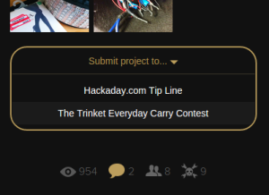
We know you all love to procrastinate with your entries, so we’re going to be offering a few perks to those who enter early and update often. Each week, we’ll throw all the entrants who have published at least one project log full of details into a drawing for a special prize from The Hackaday Store. To be considered you must officially submit your project which is accomplished through a drop-down list on the left side of your project page.

Remember, the contest isn’t just about winning a scope, a meter, or any of the other prizes. It’s about creating new Open Hardware designs that nearly anyone can build. So grab those soldering irons, load up those copies of the Arduino IDE, AVR-GCC, or WinAVR, and get hacking!

You can view the all of the contest entries in this list.

Hackaday Interview: [Grant Imahara]

We had a chance to interview [Grant Imahara] at the 2014 Electronica conference in Munich, Germany. If you don’t recognize [Grant’s] name you’ll probably recognize his face. He’s been on the cast of the television show Mythbusters for about 10 years now. We heard recently that he was leaving the show and that’s how we crossed paths with him.

[Grant] has signed on with Mouser Electronics to promote their Empowering Innovation Together program. They hosted him on a press junket at their booth and since we have a good relationship with Mouser they offered Hackaday an interview slot.

We had a lot of fun talking to [Grant]. Unfortunately the wireless microphones the Mouser videographer was using were picking up a lot of interference. This didn’t directly affect our recording setup as we were using a handheld voice recorder, but we kept getting interrupted as they tried to figure out the problem. Still, as you can see from the video below, we managed to get all the way through a few questions about [Grant’s] introduction to electronics at a young age, his first job out of school working for Industrial Light and Magic, and his advice to others who want to get into electronics and specifically robots. He mentions his early learning was guided by the books of Forrest Mims and that these days learning about electronics is no more than a keyword search away.

Better SPI Bus Design

Quick, how do you wire up an SPI bus between a microcontroller and a peripheral? SCK goes to SCK, MISO goes to MISO, and MOSI goes to MOSI, right? Yeah. You’ll need to throw in a chip select pin, but that’s pretty much it. Just wires, and it’ll most likely work. Now add a second device. The naïve solution found in thousands of Arduino tutorials do the same thing; just wires, and it’ll probably work. It’s not that simple, and Mr. Teensy himself, [Paul Stoffregen] is here to show you why.

When using multiple SPI devices, a pullup resistor on the chip select lines are a really great idea. Without a pullup, devices will work great when used alone, but will inexplicably fail when used together. It’s not magic; both devices are listening to the bus when only one should be. Putting a pullup on the CS lines keeps everything at the right logic level until a device is actually needed.

How about the MISO line? Most peripherals will disconnect their pins when the chip select signal is active, but there are exceptions. Good luck finding them. There is an easy way to check, though: just connect two resistors so the MISO line floats to a non-logic level when the CS pin is high, and check with a voltmeter. If MISO is driven high or low, you should put a small tri-state buffer in there.

That just covers hardware, and there are a few things you can do in software to reduce the number of conflicts when using more than one SPI device. One of these methods is transactions, or defining the clock rate, setting MSB or LSB first, and the polarity of the clock. Newer versions of the Arduino SPI library support transactions and the setup is very easy. In fact, transaction support in the Arduino library is something [Paul] worked on himself, and gets around the problem of having SPI-related code happening in both the main loop of a program and whenever an interrupt hits. Awesome work, and a boon to the Arduino makers around the world.